Modify 5xCree DX driver to remove blinking?

HansV

Newly Enlightened
Joined
Mar 9, 2010
Messages
70
Location
Norway
Does anyone know if you can modify the 15W DX driver (SKU 26106) for 5xCree emitters to get rid of the blinking and SOS function?
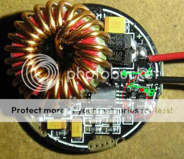
The driver board seems to have a switching regulator and a micro controller, where the labeling is removed.
Depending on how the uController controls the regulator, it should be possible to remove the blinking if that is controlled by a separate on/of signal.
This seems like a nice driver, but I don't whant the blinking. And suggestions on how to modify it is welcom.
If no one knows, I will have to go thought it with a scope when I get one that is working. I broke the current one when removing it:(
 

TorchBoy

Flashlight Enthusiast
Joined
Jan 15, 2007
Messages
4,486
Location
New Zealand
It might be best to make a product request. I don't think anyone has even figured out what chips are used or how to disable modes altogether.
 

HansV

Newly Enlightened
Joined
Mar 9, 2010
Messages
70
Location
Norway
Then I will spend some quality time in my lab and try to figure it out myself. The micro controller (Atmel?) is probebly not possible to reprogram, but the control signals could be modified. If I'm lucky, is can be done by removing a component or cutting a track.
It least, I think there will be an easy way of disabling the modes altogeather. The current regulator surely gets a control signal that sets the current, and that could be strapped to a fixed signal that is't affected by the micro controller. This could possibly also be used to change the current.

I will keep you updated on my results, if any.
 
Last edited:

uk_caver

Flashlight Enthusiast
Joined
Feb 9, 2007
Messages
1,408
Location
Central UK
Often, the drivers seem to work by the MCU PWMing a FET on the low side of the LED.
I'm not sure how easy it would be to remove the strobe effects (slow PWM) while leaving the hi/med/lo power control (fast PWM), at least not without doing something at least as complicated as programming an MCU differently.

There are a lot of people who don't like strobe modes (myself included) but that doesn't generally seem to be something that the cheap driver manufacturers pay attention to - even when they do 5 mode and 3 mode versions of a driver, the 3 mode ones often seem to be high, pathetic low, and strobe, rather than hi/med/lo at sensible power spacings.
 
Joined
Jul 15, 2007
Messages
590
Then I will spend some quality time in my lab and try to figure it out myself. The micro controller (Atmel?) is probebly not possible to reprogram, but the control signals could be modified. If I'm lucky, is can be done by removing a component or cutting a track.
It least, I think there will be an easy way of disabling the modes altogeather. The current regulator surely gets a control signal that sets the current, and that could be strapped to a fixed signal that is't affected by the micro controller. This could possibly also be used to change the current.

I will keep you updated on my results, if any.

You know, if you can find out how to just give me 'high' I'd be grateful. As much as I appreciate the dropdown it performs when the batteries start running low, I'd really rather just have high or off. The PWM isn't fast enough and I can see the blinky lights.
 

HansV

Newly Enlightened
Joined
Mar 9, 2010
Messages
70
Location
Norway
I am sure I can modify it for constant high, but it will probably require som solderig skils.
If I find out how to do it, I will post a "how to do" with pictures.
 

uk_caver

Flashlight Enthusiast
Joined
Feb 9, 2007
Messages
1,408
Location
Central UK
You know, if you can find out how to just give me 'high' I'd be grateful. As much as I appreciate the dropdown it performs when the batteries start running low, I'd really rather just have high or off. The PWM isn't fast enough and I can see the blinky lights.
I just realised I'd bought a 26106 to play around with.
Looking at the one I have, it seems to have the typical low-side FET (driven from the mode controller chip) sitting between the LED- and the +ve end of the current sense resistor.
In this image:
dx_26106_marked.jpg

The LED- is A, and the +ve end of the current sense resistor is B. Connections to the FET marked 'A081' are shown.

It's a fair bet that bridging A and B would result in removal of the power control.
 

HansV

Newly Enlightened
Joined
Mar 9, 2010
Messages
70
Location
Norway
I can confirm that the driver has a low side MOSFET, and the boost output is connected to the LED-. The LED+ is connected directly to the battery+ input. It also has a switching regulator where the markings has been removed(at least on mine) and a large rectifier diode on the output. But you seems to have two diodes in parallel, quess the large wasn't awailable or that the smaller was cheaper.
You could be right about the switching FET. I will try to verify this when I get a board that is working. That would be an easy fix to make it one mode, but will not help me getting tree modes without blinking.

Edit:
The MOSFET is a low side swtich in a standard boost configuration, switching the inductor current to ground. The inductor is in series with the + input, and the rectifier diode is connected to the LED+. The LED- is connected directly to the battery-.
The small transistor marked 'A081' on your board is connected as a switch between the LED- and the sense resistor to ground. I quess this is what controlls the output, and PWM is used to th limit the output.
Soldering between the LED+ and the sense resistor will disable this switch and make it a one mode driver. The LED- wire can also be soldered directly to the sense resistor.
The sense resistor is the large resistor near the 'B' on the picture, marked '4R7'. It is actually two reistors connected in parallel, with a total of about 0.5omh. LED current can be decreeased by removing the reistor on the top, of increased by soldering more resistors on top of it.
 
Last edited:

VanIsleDSM

Enlightened
Joined
Oct 16, 2007
Messages
649
Location
Victoria BC, Canada.
I don't think you'll be able to modify it to get rid of the blinking. The driver would have to be designed with an input you could change to adjust the programming. As it is right now, it simply receives an input and cycles to the next mode, with 5 programmed modes that's all it's going to do, you won't be able to get rid of 2 of them, without just connecting the -LED directly to the VE side of the current sensing resistor, for single mode, as mentioned by uk_caver.

The easiest way I can think of to do it, would be to just replace the controller. Program your own and replace the current one. I've thought about it already, as I was interested in doing the same thing you are, but the micros I'm used to working with only come in SOIC, not MSOP like this driver uses... which I'm sure I could have found a way around, but I eventually just abandoned this driver for my project, as it seems to be the same one that comes in the 5 CREE drop-in DX sells, and I've heard of a couple people having these burn out after a month or 2.
 

HansV

Newly Enlightened
Joined
Mar 9, 2010
Messages
70
Location
Norway
The easiest way to replace the MCU is to use a 8-pin ATtiny on a separate board and mount it on top of the driver board. Connect it to ground, supply and the output switch. It can also strapped to the PCB in stead to the current MCU, if this is removed first.
Then you are ready for programming. In circuit programming is easy on theese controllers, but you will of cause know this.
I would be able to to this, but I am not that interested in programming to make the effort.

Edit:
The 10pin controller on the board is parhaps not a micro controller at all. It has a stange pin configuration, with supply+ at pin 7 and GND at pin 3. Output to switch the current is on pin 1. Pin 4 has capacitor to ground, oscillator or hold-up for mode switching timing? My guess is that this is a ASIC, not a micro controller.
I think the only option to affect the blinking is to try to change/remove the timing capacitor.
 
Last edited:

HansV

Newly Enlightened
Joined
Mar 9, 2010
Messages
70
Location
Norway
How to make SKU 26106 15W driver a single mode!

I managed to fix the broken driver board, and have now tested it.

It works fine to move the LED- wire(black) to the sense resistor to make it single mode mode. Just desolder the wire and solder it to the resistor next to the 'B' in the picture.
The voltage across the sense reistor is 0.5V. To change the current, change the resitor value. This voltage is fixed by the regulator.

It is not possible to remove the blinking modes without changing the controller circuit:(
The effeciancy of the driver can be increased a bit by changing the switching frequency. The frequency is set by the 10kohm resistor in the bottom of the picture, on the right of the yellow capacitor. It is marked '103'
Changing the frequency can be done by soldering a 33 or 27kohm resistor in parallel, on top of the 10kohm resistor, and will increase the switching frequency to around 150kHz (from 100kHz). The resistor can also be replaced with a 6.8kohm resistor. This will give less loss in the inductor and some more loss in the switching transistor, and the input current drops a bit. Increasing the frequency more has no positive effect.
It is also possible to move the inductor away from the board if there is room for it. This will help to keep the tempratures lower. Just desolder it and solder it back were it fits. The wires can be made longer by using some cupper wire. Connection of the wires to the board can be done both ways.

Edit:
I think I will try to use the controller circuit from the SKU 7612 16-modem driver board. That has one mode group that is only low(10%)-mid(35%)-high(100%) and no blinking. If I remove the ASIC on the 15W board and glue this on upside-down I should be able to strap the connections I need from the controller to the board. This seems to be the simplest somution to the blinking problem.

I hope this helps anyone. At least I am satisfied with what I have found out.
 
Last edited:

HansV

Newly Enlightened
Joined
Mar 9, 2010
Messages
70
Location
Norway
One more driver question

I have one more driver question related to this topic:
Does anyone know what driver board is used in SKU 35241, the 1200 lumen drop-in module without modes?
My quess is that this has tha same 15W driver board where the modes are disabled. If so, it would be easy to modify it to 5 modes. It could of cause have the same driver board without the control circuits mounted, and then this will not work.
 

Techjunkie

Enlightened
Joined
Nov 16, 2007
Messages
943
Location
in the brightly lit suburbs of NYC (Long Island)
Re: How to make SKU 26106 15W driver a single mode!

...
It works fine to move the LED- wire(black) to the sense resistor to make it single mode mode. Just desolder the wire and solder it to the resistor next to the 'B' in the picture.
...

Do you mean moving the LED- wire from the red circle near A to the red circle near B in the picture below?

:EDIT: - confirmed for myself that this is the way to do it as pictured below

dx_26106_marked.jpg


Thanks
 
Last edited:

fire2727

Newly Enlightened
Joined
Dec 14, 2008
Messages
44
Re: How to make SKU 26106 15W driver a single mode!

Do you mean moving the LED- wire from the red circle near A to the red circle near B in the picture below?

:EDIT: - confirmed for myself that this is the way to do it as pictured below

dx_26106_marked.jpg


Thanks

BIG BIG thanks Techjunkie I don't understand why this worked but it does, my drop in was going into safety mode after only 3 or 4 mins on full battery and after following your "swap wire A to position B not only is it now running ok but it has also lost it' annoying modes and just runs on full 1200 lumens:rock: so again ...Thanks
 

fire2727

Newly Enlightened
Joined
Dec 14, 2008
Messages
44
Re: How to make SKU 26106 15W driver a single mode!

Just a quick question does this mean that I have no way of knowing if my batteries are running low, will I just loose all power quickly or will they start to dim + will draining them completely, damage them ?? These are the batteries http://www.ultrafire.net/showproducts.asp?id=141
 

Techjunkie

Enlightened
Joined
Nov 16, 2007
Messages
943
Location
in the brightly lit suburbs of NYC (Long Island)
Re: How to make SKU 26106 15W driver a single mode!

Just a quick question does this mean that I have no way of knowing if my batteries are running low, will I just loose all power quickly or will they start to dim + will draining them completely, damage them ?? These are the batteries http://www.ultrafire.net/showproducts.asp?id=141

The cells you linked to are protected - the built-in protection circuits will prevent you from completely draining them. Before the protection circuits kick in and completely shut off (power to) the light, you might notice that it is dimmer than usual. At the minimum Vin under load before protection kicks in (~5V), to continue providing 800mA to 5 LEDs in series, the driver would have to pull more amps than it's probably capable of. Also, at the end of their discharge, the cells might not be able to provide the current necessary. In other words, the power output of the driver would be limited by max current in (Iin) x actual voltage in (Vin.).

Depending on your use for the light and your taste, you might want max brightness until just before power runs out, or you might prefer more warning. A closer ratio of LEDs to cells will provide less warning than a higher LED to cell ratio would (because more boost required in the higher ratio requires higher input current).
 

fire2727

Newly Enlightened
Joined
Dec 14, 2008
Messages
44
Re: How to make SKU 26106 15W driver a single mode!

WOW thanks for your time and help, this is only my second mod so thanks for your help....:thumbsup:
 

tinkerman

Newly Enlightened
Joined
Oct 15, 2007
Messages
16
Re: How to make SKU 26106 15W driver a single mode!

Has anyone figured out what micro-controller is used in this board for mode setting? I want to program it with my own functionality and solder it right in, no piggy-back board or such.
 
Top