
BrianMc
Enlightened
- Joined
- Nov 4, 2009
- Messages
- 940
I will post as I go on from this point.
The dyno light on the errand bike is in this thread. Which includes a link to a ride-by video. It is to be paired with the helmet light. The Helmet light's wall beam is in this post and the light and its hood in this post in that same thread.
The Mercian has a pair of lights now. The driver is an H6Flex, reduced in diameter a mm or so to fit the Marwi housing:
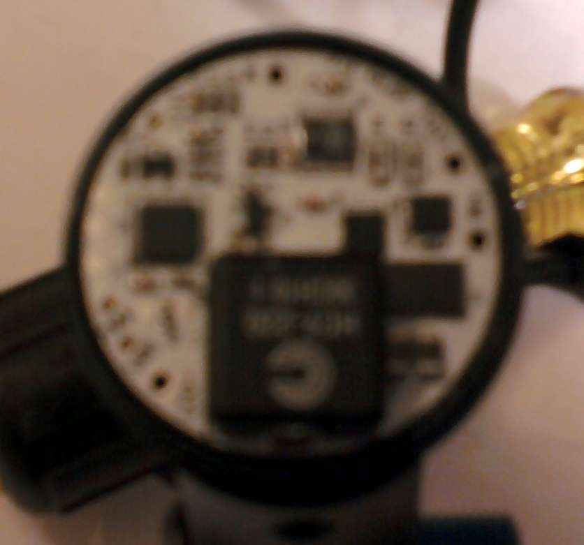
For those unfamiliar with thei light body, it has a cylindrical 1" bore, followed by a cone bore that drops to 22 mm ID at the truncated tail where a tailcone/mount fits. So the driver got copper leads removed from an old computer mother board soldered into the interface pads and angled inward so as not to short on the tapered rear of the body.
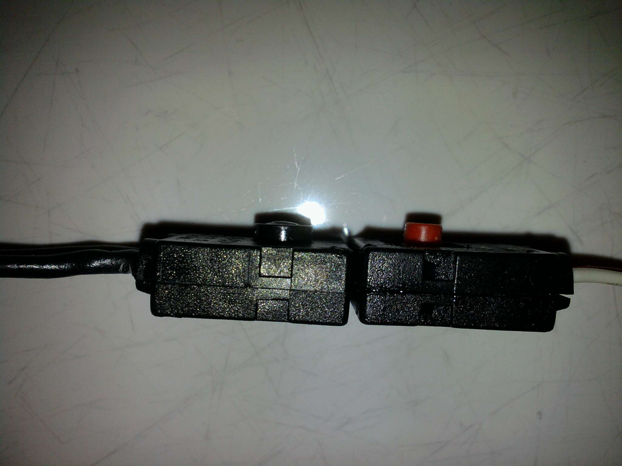
The Marwi on/off switch was opened, carved a bit and a NO MOM SPST switch from a Bflex and with the mounting legs removed, was siliconed in place. EL34 now has replacements that will save anyone else the trouble unless like me, they have some Scot in them!
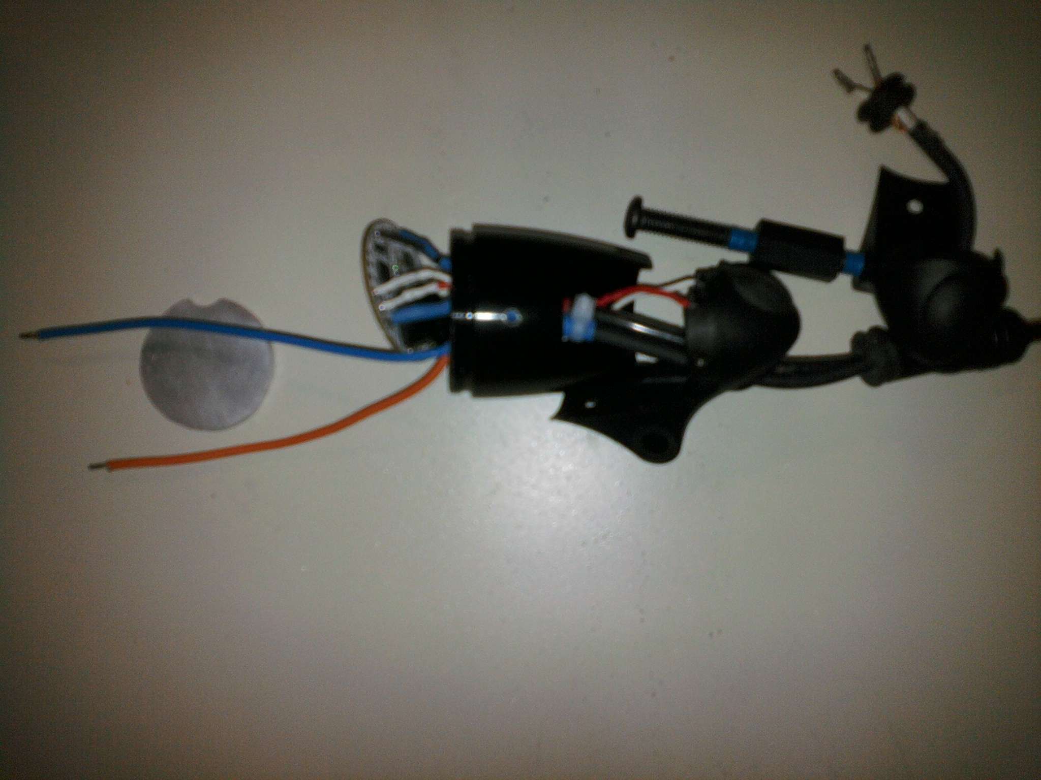
A 1/8 " (3 mm) aluminum disk was fashioned cutting it 16 sided on a saw, then filing and grinding. An LED lead passage was notched in its bottom side. It was heat taped (supplied by George of Taskled with the H6Flex, Thanks BTW, if you read this George). Then the assembly was placed with the bottom edge as far back as it would tilt to clear the LED leads past the cutout in the rear bottom of the shell. Thermal load of driver about 1.5 W maximum.
Before taping and assembly:
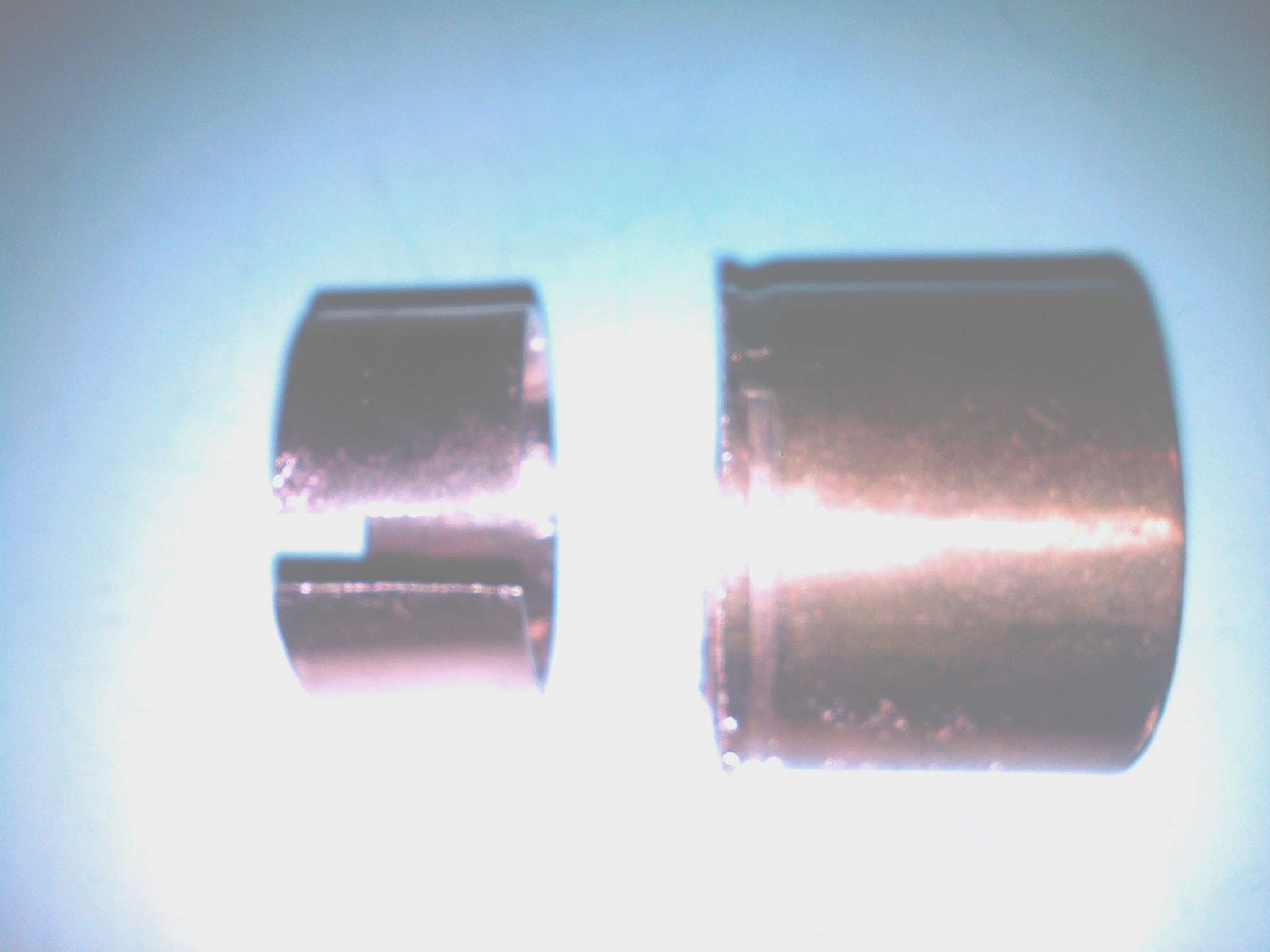
A split ring copper sleeve was fashioned from a 1 1/2" copper pipe union and reduced in circumference so when fully closed with a hose clamp it can just be slid with some force into the body:
The tail was tapered and fitted as close to exactly to the angle of the aluminum driver mount as possible by eye. A 1" pipe cap (31 mm OD) was sanded to a flat surface as was the XM-L star. Mounting and wiring holes were cut and mounting holes tapped for No. 4 screws. Brass bevel head # 4 screws had their heads reduced in diameter using a drill as a lathe. They were prefitted to clear the holes of cuttings. The cap was then cut at the same angle as the sleeve with a thickness at its top edge equal to the thickness of the end of the cap to get the 12 mm mounting depth plus MCPCB for the Eva lens. The pipe cap/LED firewall was ground/filed/sanded to an inteference fit inside the copper sleeve. The sleeve installed first with some AA, more was places on the Al disc where the copper pipie cap would sit, the LED was mounted with a little AA, wired, then the assembled firewall carefully pushed into place. A spare hole allows a long # 4 screw to be inserted to pull the assembly out, should that be needed. The EVA lens bezel and O-ring compete that light.
The negative lead from the Eva LED goes to the other light. The Iris (sans mount) lensed light needed 19 mm of depth with a thin ring of silver solder (helps thermal path to bezel, too) under it to move it forward so its back side would clear the ID of the light body without modding the lens or beveling the body more at that point. You could put a Lflex driver in the tail of this light, but not the H6 Flex..
I took a 31 mm OD copper pipe cap and flared the open end of it on a cone mandrel using the vise as a press. Slightly oversized, I ground the flare back for an interference fit to the 32.2 mm ID. This shortened the cap which helped the fit WRT the lens. I used a piece of copper from a 1 1/4 " pipe union soldered behind the flare and ground/filed/polished to an interference fit for most of the skirt of the pipe cap. The bottom of the cap deformed with a central dish when pressed. It was pushed back with a wood punch and a layer of silver solder was laid down to get a flat mounting surface for the star this also decreased the depth of the cap and helped lens placement. A 3/4" pipe cap was cut to fit the coned back of the body and bolted to the backside of the pipe cap off center towards the top of the light. AA was used sparingly in the tight interfaces but liberally where the back of the pipe cap curved away from the body (10-100 X better path than air). This light has no temperature monitoring so MUST run at least as cool as the one with the driver. Not having a driver saves about 0.7 watt of input, but the cap did not quite bridge the ID transition point (thin) of the light body so I added the second reversed smaller pipe cap with its skirt cut into four fingers to provide ample thermal path into the tail. The Iris has a central hole, so a glass lens cover was used. This holds the bezel out from its fully seated position, so I may see a thin piece of polycarbonate for this job.
The competed light mounted:
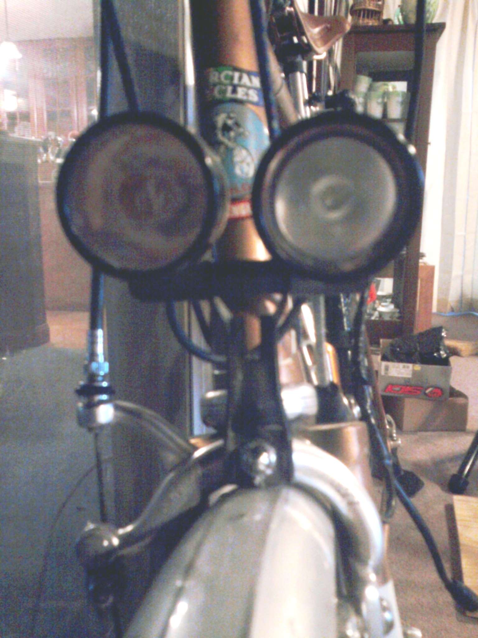
By brianmcb at 2011-03-25
Rode for I mile last night with them between the 1400 and level 3 (350 mA?) levels. Somewhere around 900 lumens out the front at 1400 is more than adequate. The other level was not after what I have gotten used to having, but way more light up close thatn I remember from my old HID. Will try 2 A, at some point, of course. Curious if they will trip the 50 C cutoff in the driver at 3 A while riding, too. That level would be nice off-road. Will have to practice my lean down and switch to low level while riding technique. At 1.4 A, Each light is below the 5 watt German standards for a 12 volt light, but together over 8 watts. They were intended to be aimed with their hotspots on the road and hoods to block the higher angle spill from oncoming drivers and pedestrians and provide a light path to where the helmet light takes over.
We will see.
So let the experimentation/night riding and recording it begin. First up a revisit of the ride by witha focused camera and appropriate camera and headlight angles.
The dyno light on the errand bike is in this thread. Which includes a link to a ride-by video. It is to be paired with the helmet light. The Helmet light's wall beam is in this post and the light and its hood in this post in that same thread.
The Mercian has a pair of lights now. The driver is an H6Flex, reduced in diameter a mm or so to fit the Marwi housing:
For those unfamiliar with thei light body, it has a cylindrical 1" bore, followed by a cone bore that drops to 22 mm ID at the truncated tail where a tailcone/mount fits. So the driver got copper leads removed from an old computer mother board soldered into the interface pads and angled inward so as not to short on the tapered rear of the body.
The Marwi on/off switch was opened, carved a bit and a NO MOM SPST switch from a Bflex and with the mounting legs removed, was siliconed in place. EL34 now has replacements that will save anyone else the trouble unless like me, they have some Scot in them!
A 1/8 " (3 mm) aluminum disk was fashioned cutting it 16 sided on a saw, then filing and grinding. An LED lead passage was notched in its bottom side. It was heat taped (supplied by George of Taskled with the H6Flex, Thanks BTW, if you read this George). Then the assembly was placed with the bottom edge as far back as it would tilt to clear the LED leads past the cutout in the rear bottom of the shell. Thermal load of driver about 1.5 W maximum.
Before taping and assembly:
A split ring copper sleeve was fashioned from a 1 1/2" copper pipe union and reduced in circumference so when fully closed with a hose clamp it can just be slid with some force into the body:
The tail was tapered and fitted as close to exactly to the angle of the aluminum driver mount as possible by eye. A 1" pipe cap (31 mm OD) was sanded to a flat surface as was the XM-L star. Mounting and wiring holes were cut and mounting holes tapped for No. 4 screws. Brass bevel head # 4 screws had their heads reduced in diameter using a drill as a lathe. They were prefitted to clear the holes of cuttings. The cap was then cut at the same angle as the sleeve with a thickness at its top edge equal to the thickness of the end of the cap to get the 12 mm mounting depth plus MCPCB for the Eva lens. The pipe cap/LED firewall was ground/filed/sanded to an inteference fit inside the copper sleeve. The sleeve installed first with some AA, more was places on the Al disc where the copper pipie cap would sit, the LED was mounted with a little AA, wired, then the assembled firewall carefully pushed into place. A spare hole allows a long # 4 screw to be inserted to pull the assembly out, should that be needed. The EVA lens bezel and O-ring compete that light.
The negative lead from the Eva LED goes to the other light. The Iris (sans mount) lensed light needed 19 mm of depth with a thin ring of silver solder (helps thermal path to bezel, too) under it to move it forward so its back side would clear the ID of the light body without modding the lens or beveling the body more at that point. You could put a Lflex driver in the tail of this light, but not the H6 Flex..
I took a 31 mm OD copper pipe cap and flared the open end of it on a cone mandrel using the vise as a press. Slightly oversized, I ground the flare back for an interference fit to the 32.2 mm ID. This shortened the cap which helped the fit WRT the lens. I used a piece of copper from a 1 1/4 " pipe union soldered behind the flare and ground/filed/polished to an interference fit for most of the skirt of the pipe cap. The bottom of the cap deformed with a central dish when pressed. It was pushed back with a wood punch and a layer of silver solder was laid down to get a flat mounting surface for the star this also decreased the depth of the cap and helped lens placement. A 3/4" pipe cap was cut to fit the coned back of the body and bolted to the backside of the pipe cap off center towards the top of the light. AA was used sparingly in the tight interfaces but liberally where the back of the pipe cap curved away from the body (10-100 X better path than air). This light has no temperature monitoring so MUST run at least as cool as the one with the driver. Not having a driver saves about 0.7 watt of input, but the cap did not quite bridge the ID transition point (thin) of the light body so I added the second reversed smaller pipe cap with its skirt cut into four fingers to provide ample thermal path into the tail. The Iris has a central hole, so a glass lens cover was used. This holds the bezel out from its fully seated position, so I may see a thin piece of polycarbonate for this job.
The competed light mounted:
By brianmcb at 2011-03-25
Rode for I mile last night with them between the 1400 and level 3 (350 mA?) levels. Somewhere around 900 lumens out the front at 1400 is more than adequate.
The other level was not after what I have gotten used to having, but way more light up close thatn I remember from my old HID. Will try 2 A, at some point, of course. Curious if they will trip the 50 C cutoff in the driver at 3 A while riding, too. That level would be nice off-road. Will have to practice my lean down and switch to low level while riding technique. At 1.4 A, Each light is below the 5 watt German standards for a 12 volt light, but together over 8 watts. They were intended to be aimed with their hotspots on the road and hoods to block the higher angle spill from oncoming drivers and pedestrians and provide a light path to where the helmet light takes over.We will see.
So let the experimentation/night riding and recording it begin. First up a revisit of the ride by witha focused camera and appropriate camera and headlight angles.


 But I recently received a gift that will cover it and the accessories (and maybe fund a support level here?). I have a bad feeling the file editing grind might force a new computer, though. I have asked a vendor if they have video showing its night use on streets not full of neon and overhead lights, maybe showing a car's headlight beams. As far as I can see other than being one unit and maybe a bit heavy on a helmet, it all the video camera I can imagine needing.

