
Old-Lumens
Newly Enlightened
I'm doing just a shortie post here...
This is a 2D Maglite that I cut down to use 3AA batteries. (I believe a smart Li-ion type person would substitute with a 26650 or 32650 "C or D" sized Li-ion battery).
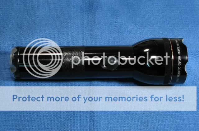
My method of cutting down the barrel was using the human lathe method. I cut out 2" of the center of the body. Then I used a rotary tool to open up the ID of one piece of the barrel and I used files to remove material from the OD of the other piece. The fit was ok. Then I used JB Weld on both pieces to make the joint strong (I added copper filings into the JB Weld, to help conductivity). After that, I drilled three holes in the joint and drove three brass pins in them. Now it's sturdy!
Here's a few shots of the other mods I did to this light and some of the components:
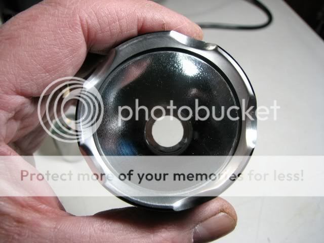
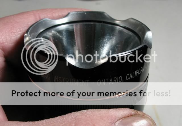
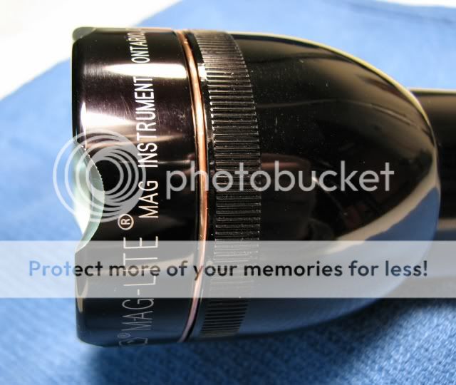
Crenulated Bezel
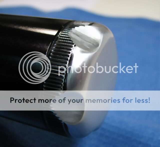
Also modded the tailcap
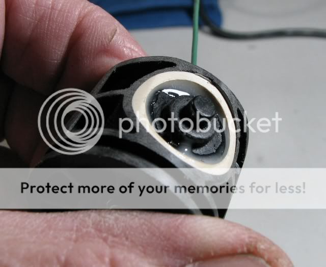
Switch is modded to use a Judco switch instead of the stock switch. Much modding was necessary using a rotary tool and a PVC ring to still have a base for the stock rubber cap to sit on.
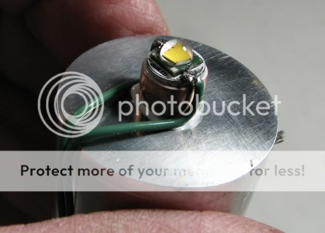
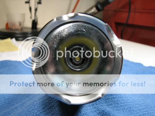
Pedestal for the LED, so the light is adjstable just like original
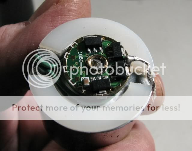
105C driver 2.8A, set for 3 mode (High, Medium, Low)
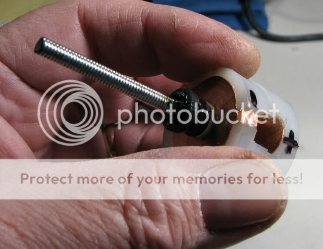
Homemade 3AA Battery holder. Copper, no springs.
And here is the finished light:
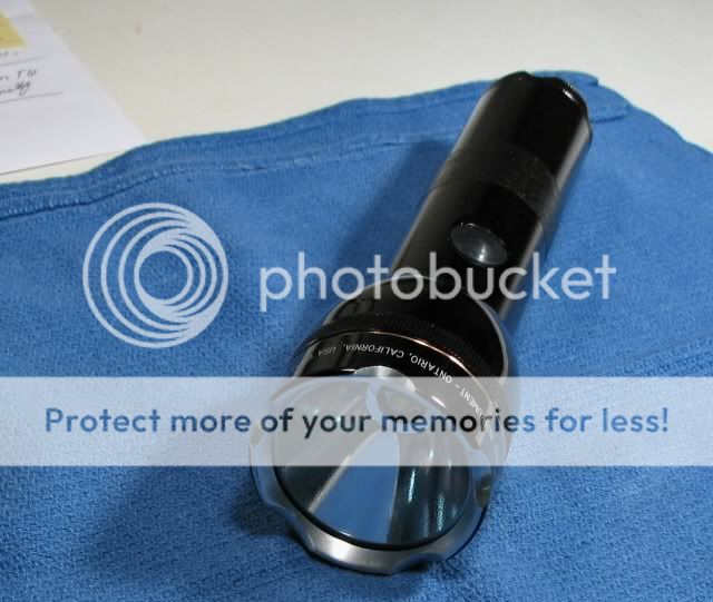

Paint covers the section where it was put together. The black with copper that I normally use.
List of materials:
2d Maglite Incan
XML-T6 emitter
1-3/8 Aluminum round stock for the heatsink
20ga copper shim
1" round UHMW plastic rod stock for the battery holder
Misc threaded rod, nuts, copper, etc.
SST-50 Reflector (light OP finish)
Glass Lens
105C 2.8A circuit board
Teflon Wire
Judco Switch
Artic Alumina
2 Part Epoxy
JB Weld
Copper trim ring on the head
What else??
Here's a couple indoors beam shots:

Low

Medium

High
I used a brass pin through the side of the body & thru the aluminum heatsink to make ground for the system. It is just below the threads and can't be seen when the head is in place.
The Judco switch was used, to have control of changing modes.
The beam does not have much spill and a large spot. I hope to be able to do night shots outdoors sometime.
This light goes up for sale as always. I use the money to be able to build other mods. It's the wat I can keep having something to occupy my time.
That's all
This is a 2D Maglite that I cut down to use 3AA batteries. (I believe a smart Li-ion type person would substitute with a 26650 or 32650 "C or D" sized Li-ion battery).
My method of cutting down the barrel was using the human lathe method. I cut out 2" of the center of the body. Then I used a rotary tool to open up the ID of one piece of the barrel and I used files to remove material from the OD of the other piece. The fit was ok. Then I used JB Weld on both pieces to make the joint strong (I added copper filings into the JB Weld, to help conductivity). After that, I drilled three holes in the joint and drove three brass pins in them. Now it's sturdy!
Here's a few shots of the other mods I did to this light and some of the components:
Crenulated Bezel
Also modded the tailcap
Switch is modded to use a Judco switch instead of the stock switch. Much modding was necessary using a rotary tool and a PVC ring to still have a base for the stock rubber cap to sit on.
Pedestal for the LED, so the light is adjstable just like original
105C driver 2.8A, set for 3 mode (High, Medium, Low)
Homemade 3AA Battery holder. Copper, no springs.
And here is the finished light:
Paint covers the section where it was put together. The black with copper that I normally use.
List of materials:
2d Maglite Incan
XML-T6 emitter
1-3/8 Aluminum round stock for the heatsink
20ga copper shim
1" round UHMW plastic rod stock for the battery holder
Misc threaded rod, nuts, copper, etc.
SST-50 Reflector (light OP finish)
Glass Lens
105C 2.8A circuit board
Teflon Wire
Judco Switch
Artic Alumina
2 Part Epoxy
JB Weld
Copper trim ring on the head
What else??
Here's a couple indoors beam shots:
Low
Medium
High
I used a brass pin through the side of the body & thru the aluminum heatsink to make ground for the system. It is just below the threads and can't be seen when the head is in place.
The Judco switch was used, to have control of changing modes.
The beam does not have much spill and a large spot. I hope to be able to do night shots outdoors sometime.
This light goes up for sale as always. I use the money to be able to build other mods. It's the wat I can keep having something to occupy my time.
That's all
Last edited:
")