Help fixing JetBeam Jet-III Pro Ti 2008 light

LuxLuthor

Flashaholic
Joined
Nov 5, 2005
Messages
10,654
Location
MS
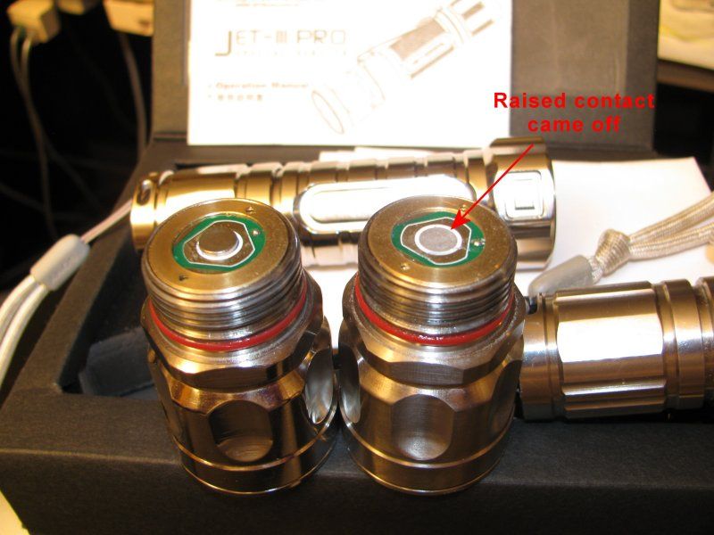
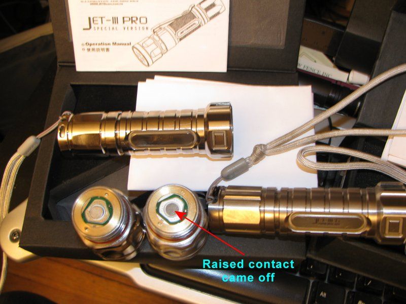
I see that BugOutGearUSA is no longer selling JetBeam (where I bought these models in 2008), and had a minor problem with one when changing batteries last night. The bottom of the LED Driver circuit has a raised metal disc (like a thin 5mm diameter Neodymium magnet) that came off as shown in these two photos. Anyone know if there is a simple do-it-myself fix for this, or if JetBeam has a service available in the USA to fix it? Thanks guys.

JetbeamJet-IIIProTi-a_zpsd57b91c3.jpg


JetbeamJet-IIIProTi-b_zps732020e1.jpg


aau007

Enlightened
Joined
Sep 12, 2010
Messages
448
Tiny bit of wire glue and press on the board really tight?

Or sell me the light dirt cheap as parts only. :D
 

Chodes

Flashlight Enthusiast
Joined
Jun 5, 2008
Messages
1,092
Location
Australia
LuxLuthor definitely has those skills.

In fact I'm a bit surprised he has not just DIY fixed already.

The brass pills available on this page look suitable for re soldering:
http://intl-outdoor.com/components-gears-c-57_106.html?page=2&sort=20a

Description: Brass pill for drivers as anode contact or cell anode contact modification. Alternative to springs, high current flow. Features: Material: Brass Thickness: 1mm Diameter: 6mm Shipping is free for any quantity purchased...

They have 2mm and 1mm thick available
 

LuxLuthor

Flashaholic
Joined
Nov 5, 2005
Messages
10,654
Location
MS
It actually looks like they used a thin Neodymium magnet and it fractured in half, leaving that dark gray magnet material behind. It is still conductive.

My concerns were whether that surface would take solder, and if heat would damage internals of pill. I could just use wire epoxy glue with another Neodymium magnet in place. I took another couple closeups.

Jetbeam1_zpscb751602.jpg


Jetbeam2_zps6b344708.jpg


Last edited:

Fireclaw18

Flashlight Enthusiast
Joined
Mar 16, 2011
Messages
2,408
I attached a small copper disk to the back of a driver in pretty much exactly the same situation as what the original poster is experiencing.

First I applied solder flux to the back of the driver and the top of the disk. Then I applied a layer of low-temperature Chipquick solder paste. Last step was to hold my soldering iron to the back of the disk. The instant the solder paste melts, remove the iron. The key is not to leave the iron on long or the heat could destroy the driver. It works great and I've had no trouble.

If you want to try another magnet with epoxy, I suggest you put the magnet into place first and then use the epoxy around the sides of the magnet. That you don't have to worry about epoxy getting between the magnet and the driver.

I'm not sure about using conductive epoxy directly between the magnet and driver for a high-current application like a flashlight. I suspect that the epoxy might have a lot more resistance than metal-metal contact and could degrade performance.
 
Last edited:

LuxLuthor

Flashaholic
Joined
Nov 5, 2005
Messages
10,654
Location
MS
Lux could you replace the magnet using Conductive Glue.

Norm

That was my thought, as what remains on the PCB has that same dark, granular carbon feel to it, like a rough chalk board...so maybe that was what Jetbeam originally used? But then as I'm not sure what they used, I had that same concern Fireclaw just mentioned regarding the resistance factor. I don't know how many ma are being drawn by this light...but judging by the long run time, probably not a lot. I had never used the Chipquick solder paste, and don't want to ruin the driver. Interimly, if I use a 18650 with a raised + contact, it works...so maybe if I don't hear from someone who knows if they used the wire/conductive glue I should just leave it alone.

Anyone know if Jetbeam has any effective USA support/service options?
 

Chodes

Flashlight Enthusiast
Joined
Jun 5, 2008
Messages
1,092
Location
Australia
Looks like I went of half cocked with repair (I was thinking just solder something to the pill)

I think only purpose of missing part is to ensure that flat top cells will have a small gap for safety - don't want edge of cell touching brass ring on pill if shrink wrap get's damaged. If using button cell, the cell button provides the gap. So if sticking to button cells works, no problem for you.

I have a Jet 3 pro, same light just Al. Max current I have measured is about 1.3A at tailcap, would not be too much variation replacing mmeter with switch.
I have some wire glue. I never actually used it, was told by a few people it's pretty poor resistance wise.
 

LuxLuthor

Flashaholic
Joined
Nov 5, 2005
Messages
10,654
Location
MS
Looks like I went of half cocked with repair (I was thinking just solder something to the pill)

I think only purpose of missing part is to ensure that flat top cells will have a small gap for safety - don't want edge of cell touching brass ring on pill if shrink wrap get's damaged. If using button cell, the cell button provides the gap. So if sticking to button cells works, no problem for you.

I have a Jet 3 pro, same light just Al. Max current I have measured is about 1.3A at tailcap, would not be too much variation replacing mmeter with switch.
I have some wire glue. I never actually used it, was told by a few people it's pretty poor resistance wise.

Thanks for all your help and suggestions.

This other product I previously had gotten seems to have a better reputation and lists its lower resistance & other characteristics, sold for $31 at Amazon here.
 
Top