
Techjunkie
Enlightened
*update #3* The taicap resistors and improved regulator heatsinking now have the light dialed in perfectly. I can run on max current until the head is uncomfortable to hold without the regulators overheating. See updates in post #31.
*update #2* The KD V2 regulators overheat way too easily in this application (maybe it's the 380mA 7135 vs the 350mA ones) have to rework the drivers (having deja vu here. when will I ever learn?)
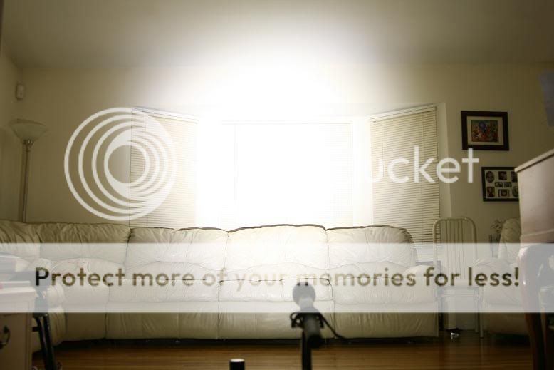
*update* Build complete. Beamshots in post #11.
I'm finally starting the build log for this light, but the truth is I've been collecting parts for it for months now. The finished specs will be:
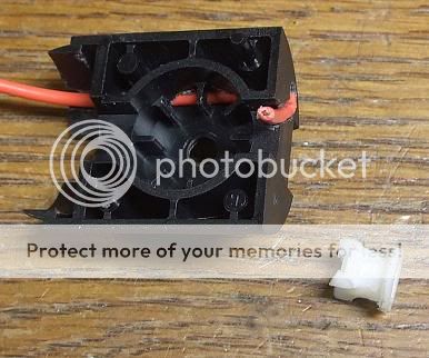
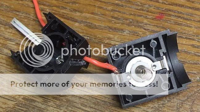
I've got a new twist on my Everyman's recipe from my other builds. It occurred to me that LED positive can be connected directly to the battery instead of coming across the switch. When the regulators are off, the circuit is broken. This reduces resistance by removing the Mag switch from the LED circuit and also saves the switch from carrying 12A of current. I've tested this already with one XML, one IMR22650, and one KD V2 regulator configured for H-M-L. The only oddity that I noticed in this configuration was that the mode board's memory seemed to take a split second to kick in, causing a quick flash of high mode when turning on in, or changing to, low mode. A light that I built using the same components and mode group, but with a traditional tail switch doesn't exhibit the mode switch flash. I'm not concerned at the moment.
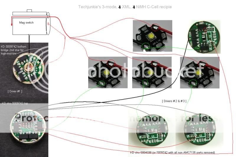
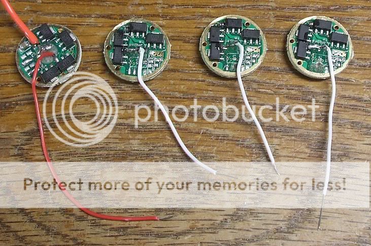
A quick mock-up using the old diagram as a starting point (in actuality, the new V2 regulators with 380mA per 7135 will be used:
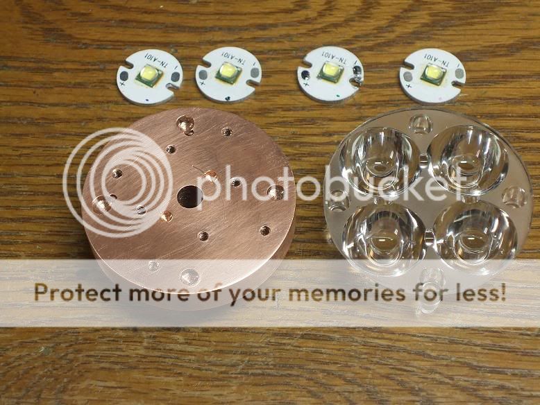
Some pics of the mechanical parts of the build so far...
5000K emitters from DigiKey SMD soldered to 16.5mm boards from KD (top)
PES-C Cu heatsink machined flat, drilled and tapped (left)
DX Quad optic with edge trimmed to recess inside Mag C head (right)
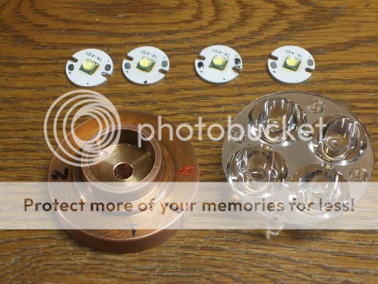
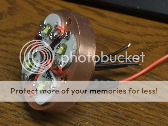
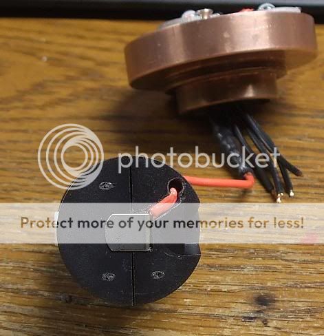
Underside of heatsink shows color coding corresponding to dots on MCPCBs. This little trick allows me to align the LEDs in the same orientation as when measurements for holes were taken.
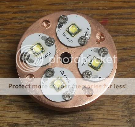
MCPCBs fully mounted with AS5 and #3 screws. What you don't see here is that all 8 screws had to be trimmed in length and deburred and all 8 slots in the sides of the MCPCBs had to be made wider with a 3/32" bit. (What a pain.)
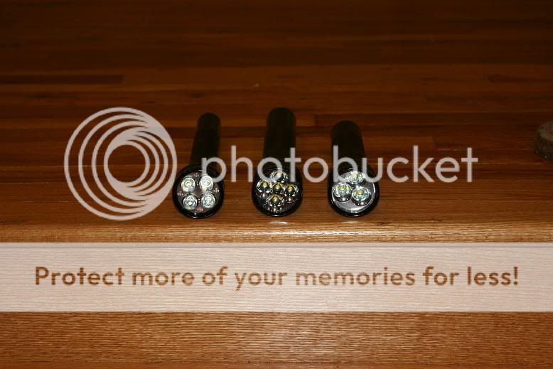
Closeup of the optic positioned over the LEDs. The holes that the four pegs stand in had to be drilled to 2mm depth to position the optic the same height over the MCPCBs to simulate the wider part of the pegs sitting on the MCPCBs. This puts the optic at the correct/optimal focal distance from the LED surface.
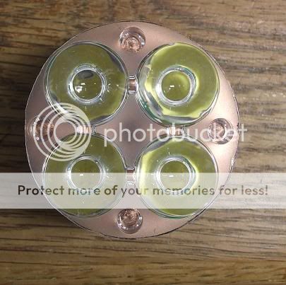
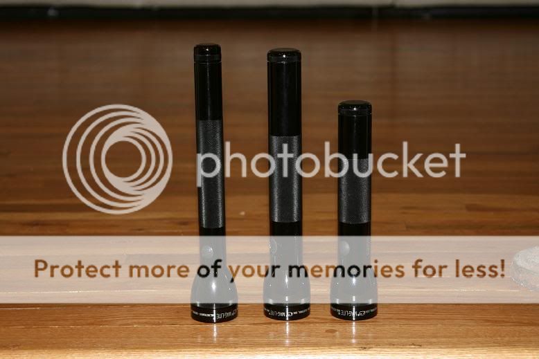
A preview of what it will look like fully assembled. (Nothing's wired up yet.)
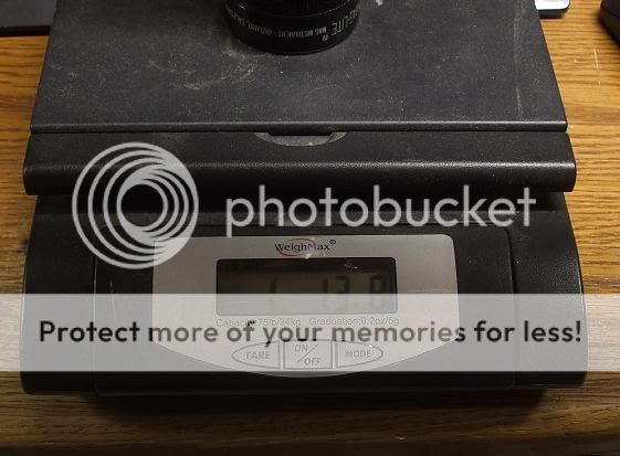
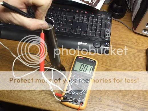
I decided to weigh it with everything but the drivers installed. This sucker's heavy - almost 2 lbs.!
Build completed. See posts 9-11.
*update #2* The KD V2 regulators overheat way too easily in this application (maybe it's the 380mA 7135 vs the 350mA ones) have to rework the drivers (having deja vu here. when will I ever learn?)
*update* Build complete. Beamshots in post #11.
I'm finally starting the build log for this light, but the truth is I've been collecting parts for it for months now. The finished specs will be:
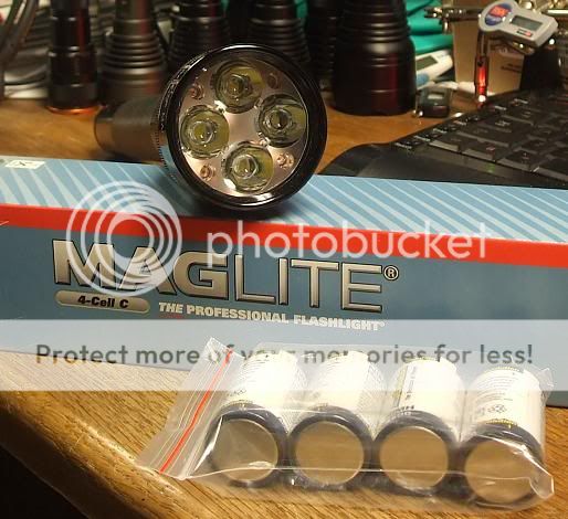
- Mag 4C
- Glass lens
- Quad Optic (edges trimmed)
- Cu PES C heatsink machined flat (drilled & tapped)
- 4x 5000K CREE XM-L (my new favorite tint)
- One individual 3.04A regulator for each LED, mode slaved (KD V2 regs with 380mA per 7135)
- 3 modes: very low, medium very high (my new favorite mode group thanks to these new V2 boards)
- 4x AccuPower Evolution NiMH LSD C cells 4500mAH (4.8V pack voltage ensures full power available through nearly the entire discharge)
- 12A draw at the tail, mere milliamps through the mag switch
I've got a new twist on my Everyman's recipe from my other builds. It occurred to me that LED positive can be connected directly to the battery instead of coming across the switch. When the regulators are off, the circuit is broken. This reduces resistance by removing the Mag switch from the LED circuit and also saves the switch from carrying 12A of current. I've tested this already with one XML, one IMR22650, and one KD V2 regulator configured for H-M-L. The only oddity that I noticed in this configuration was that the mode board's memory seemed to take a split second to kick in, causing a quick flash of high mode when turning on in, or changing to, low mode. A light that I built using the same components and mode group, but with a traditional tail switch doesn't exhibit the mode switch flash. I'm not concerned at the moment.
A quick mock-up using the old diagram as a starting point (in actuality, the new V2 regulators with 380mA per 7135 will be used:
Some pics of the mechanical parts of the build so far...
5000K emitters from DigiKey SMD soldered to 16.5mm boards from KD (top)
PES-C Cu heatsink machined flat, drilled and tapped (left)
DX Quad optic with edge trimmed to recess inside Mag C head (right)
Underside of heatsink shows color coding corresponding to dots on MCPCBs. This little trick allows me to align the LEDs in the same orientation as when measurements for holes were taken.
MCPCBs fully mounted with AS5 and #3 screws. What you don't see here is that all 8 screws had to be trimmed in length and deburred and all 8 slots in the sides of the MCPCBs had to be made wider with a 3/32" bit. (What a pain.)
Closeup of the optic positioned over the LEDs. The holes that the four pegs stand in had to be drilled to 2mm depth to position the optic the same height over the MCPCBs to simulate the wider part of the pegs sitting on the MCPCBs. This puts the optic at the correct/optimal focal distance from the LED surface.
A preview of what it will look like fully assembled. (Nothing's wired up yet.)
I decided to weigh it with everything but the drivers installed. This sucker's heavy - almost 2 lbs.!
Build completed. See posts 9-11.
Last edited:
")


 nice work!
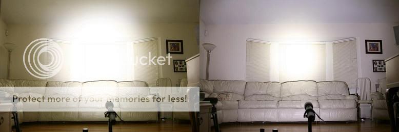
 I just read the specs of these new V2 regulators:
 .
.