
Techjunkie
Enlightened
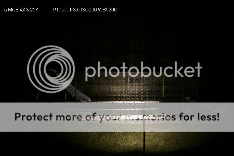
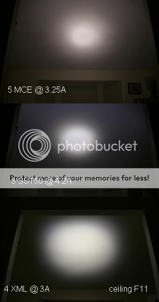
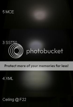
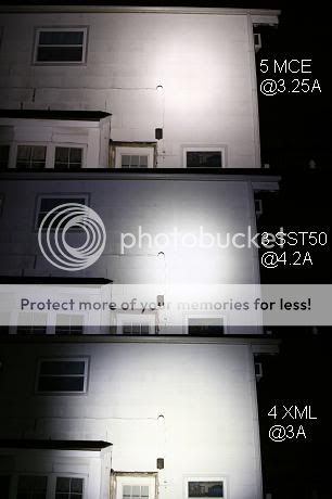
Re: Beamshots: Quad XML Mag 4C (Optics NiMH 3-mode) new everyman's recipe
I did some rough estimate math and calculated that if the cells are dropping to 1.05 Vout under load (guessing at this figure based on what Eneloop AAs and Titanium PowerMax 1800 AAs drop to under 10A load ), that's 4.2V. Each emitter needs only ~3.3V to reach the target max current. That means to maintain max output, the regulators need to drop .9V @ 12A, and shed 10.8Watts of heat. I realize now that's asking a bit too much considering the heatsinking available to them in this space.
I've just ordered some 5W 0.15 ohm cement resistors. Two placed in parallel in the tailcap will equal one 10W 0.075 ohm resistor. Using the math above, that should drop the voltage on the pack 0.9V @ 12A and land the target voltage right where it needs to be, leaving the regulators with little to no work to do.
12A = .9V/0.075ohm
0.075ohm = .9V/12A
I'll have to heatsink the resistors in the tailcap as best I can, considering that they'll be run slightly over spec when the batteries are fully charged and the light is on high.
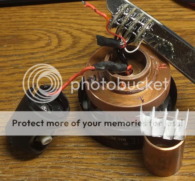
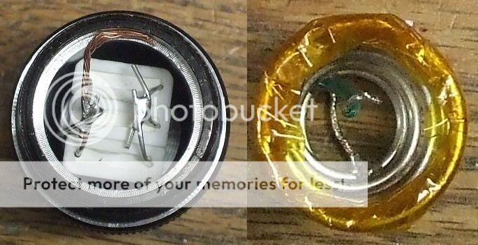
Before arriving at this (latest) conclusion, I had already desoldered the regulators, from when I was planning to replace them with the older versions. While I'm waiting for the resistors to arrive, I'll see if I can solder all four into a short section of copper tube, which should improve their heatsinking somewhat.
Wish me luck.
*EDIT* I think I can fit 3 x 0.22 ohm 5W resistors in parallel in the tailcap. At 12A current, they'll collectively drop voltage 0.88v, leaving the regulators very little work to do. Each resistor will run at 3.5W, which will be in spec for them. Each regulator will have to burn off 0.48W, or 1.44W collectively, which is waaaay cooler than the 10.8W they'd have to burn without the resistors.
I did some rough estimate math and calculated that if the cells are dropping to 1.05 Vout under load (guessing at this figure based on what Eneloop AAs and Titanium PowerMax 1800 AAs drop to under 10A load ), that's 4.2V. Each emitter needs only ~3.3V to reach the target max current. That means to maintain max output, the regulators need to drop .9V @ 12A, and shed 10.8Watts of heat. I realize now that's asking a bit too much considering the heatsinking available to them in this space.
I've just ordered some 5W 0.15 ohm cement resistors. Two placed in parallel in the tailcap will equal one 10W 0.075 ohm resistor. Using the math above, that should drop the voltage on the pack 0.9V @ 12A and land the target voltage right where it needs to be, leaving the regulators with little to no work to do.
12A = .9V/0.075ohm
0.075ohm = .9V/12A
I'll have to heatsink the resistors in the tailcap as best I can, considering that they'll be run slightly over spec when the batteries are fully charged and the light is on high.
Before arriving at this (latest) conclusion, I had already desoldered the regulators, from when I was planning to replace them with the older versions. While I'm waiting for the resistors to arrive, I'll see if I can solder all four into a short section of copper tube, which should improve their heatsinking somewhat.
Wish me luck.
*EDIT* I think I can fit 3 x 0.22 ohm 5W resistors in parallel in the tailcap. At 12A current, they'll collectively drop voltage 0.88v, leaving the regulators very little work to do. Each resistor will run at 3.5W, which will be in spec for them. Each regulator will have to burn off 0.48W, or 1.44W collectively, which is waaaay cooler than the 10.8W they'd have to burn without the resistors.
Last edited:


")