You are using an out of date browser. It may not display this or other websites correctly.
You should upgrade or use an alternative browser.
You should upgrade or use an alternative browser.
H6Flex 6.6Amp Adjustable Buck
- Thread starter georges80
- Start date

georges80
Flashlight Enthusiast
As an electronics tinkerer I was interested in your testing and programming jig. It looks like you have some spring loaded pins that contact the main driver board for programming and test points.
Is this whats going on, or could you explain a little bit more about your development process? How did you go about making your test jig?
...
Yes, they are called pogo pins and are available with different style tips and have internal springs. They were developed specifically for testing boards etc. I chose a conical sharp tip style so that I have a few thruholes (input power, output etc) that some of the pogo pins key into to 'center' the jig. The rest of the pogo pins can then just hit small pads that are only on one side of the board - so I don't give up anything on the other side of the board.
A closer picture of one of the jigs next to some drivers from yesteryear:

When I lay out a board to send to a prototype PCB house I also lay out a test/programming jig PCB and send that on the same panel. I use a proto PCB house that allows panelization of different designs on a single run - that way I can test a few different designs and also run the jigs at the same time. Works out pretty cheap and for $60 - $80 I can get a few different layouts/designs on the same panel.
The jigs make it so easy to program and test boards versus trying to use chip clips (which are pretty hopeless) and also allow the use of QFN packages that have no 'pins' to clip to.
And, as you say, with the pogo pins and jigs you don't have to have the cost of programming/test headers on each board you ship - which is something I did on my earlier driver boards (the original uFlex and early nFlex drivers).
cheers,
george.
SUBjohan
Newly Enlightened
Sweet, I have been waiting for this one!
I will need at least 4 of these (I asume you don´t take reservations:candle") .
.
If you like I can do some extensive efficiency measurements with all calibrated meters ofcourse.
Greetz Johan
I will need at least 4 of these (I asume you don´t take reservations:candle
.If you like I can do some extensive efficiency measurements with all calibrated meters ofcourse.
Greetz Johan
georges80
Flashlight Enthusiast
george that is so cool to see how to develope the boards, thanks for sharing.
What are those old boards from yesteryear? Just curious
drew
The old boards are the bbflex drivers that were used my Mr Bulk in the Chameleon lights. Basically a single li-ion buck/boost driver for a single LED. It could drive up to 1.2A. It provided the UIP feature set back before the larger capacity attiny25/45/85 series was available. The firmware in the bbflex was all assembler code - versus with the attiny85 all my code is in C - much easier to debug and add features etc.
Subjohan. No, I don't take pre-orders or pre-pays, never have, never will etc etc.
For efficiency, it will run VERY similar to the H6CC given the switcher core is directly pulled from the H6CC. You can see the efficiency curves in the H6CC thread in this subforum.
cheers,
george.
george,
Thanks so much for your description and photos of the pogo pin setup and the programming pads. I get it!!! Its a friggen revelation.
Oh pogo pins where have you been all my life. Oh, right here in my desk drawer in my office. No really, I work in an engineering school and the pogo pins have been floating around since day one. It just never really completly clicked until your post. I think these things just may very well change my life, seriously! Thanks.
For anyone else who is interested, I did find this great article on using the pogo pins to construct some fancy test jigs over on the sparkfun website. Its definately worth looking at if you are intrested in using these pins.
http://www.sparkfun.com/commerce/tutorial_info.php?tutorials_id=138
Last edited:
dan1million
Newly Enlightened
any updates on this one George
Massive fan of the previous work hipflex in particular. cant wait for this one !
Massive fan of the previous work hipflex in particular. cant wait for this one !
georges80
Flashlight Enthusiast
any updates on this one George
Massive fan of the previous work hipflex in particular. cant wait for this one !
The proto is working well. I have to do one more proto run to test a change in ucontroller (due to needing an extra pin for controlling the power management).
I have a few other protos I need to test so within a week I'll do a proto run.In about 2 weeks and I'll have confirmed the new layout and then be ready to run production boards.
So, I'd say about 4 weeks before production h6flex boards are available.
I've been busy working on a wireless LED warning system for motorbike racing the past few weeks (was at Infineon Raceway last w/end running a demo and doing tests during the event there). So, that's taken priority over other projects...
cheers,
george.
dan1million
Newly Enlightened
Thats great news. hope the other project goes well also.
I've been busy working on a wireless LED warning system for motorbike racing the past few weeks (was at Infineon Raceway last w/end running a demo and doing tests during the event there). So, that's taken priority over other projects...
cheers,
george.
Lucky dog!
PCC
Flashlight Enthusiast
Any updates as to when these will be available?
georges80
Flashlight Enthusiast
Soon, soon
I sent out for another protopcb run last week, should have boards in hand in the next few days (likely Tuesday). I already have the parts on hand to assemble the prototype.
So, by the end of this week I'll have tested the new layout and uController and at that point will kick off a production PCB run that will take about 2 weeks to deliver.
I'll keep this thread updated as I run the v2 prototype through its paces.
If all goes to plan (and it should, given the testing so far), the h6flex should be available by the end of this month (June).
cheers,
george.
georges80
Flashlight Enthusiast
Ok, prototype boards arrived yesterday. Got one assembled and had a bit of time to port the code to the new uController I'm using for this board.
Little bit of debugging to fix a few porting errors and I've got the board running on the lowest current table (1.4A). Low runs around 20mA. More testing to do to verify the standard flex features (voltage monitoring/warning, temperature monitoring etc).
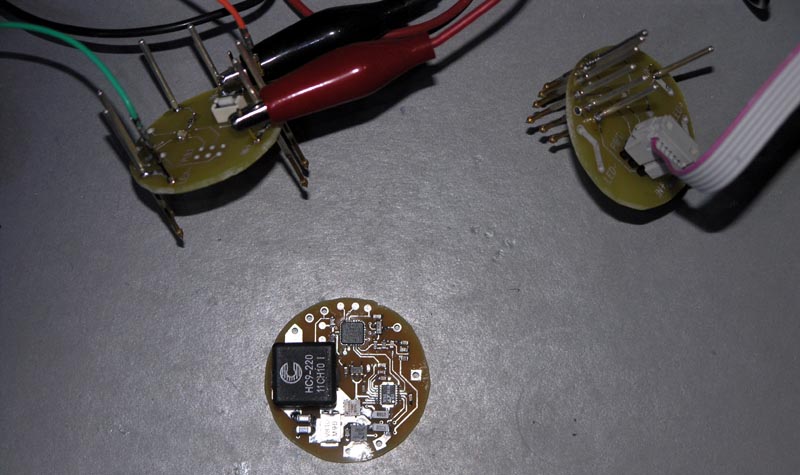
First picture shows the new prototype and two jigs (top left is the test jig, top right is programming jig).
Closeup of the lastest prototype sporting the new uController. The main reason for going with the new uC (still an Atmel AVR device) was that I needed one more i/o pin and this unit provides lots of i/o's and in a smaller physical package. The extra i/o was needed to provide PWM control for reliably achieving the lowest current levels (<200mA) with decent tint control. On my previous drivers I could use a single pin for power management and PWM control, but the switcher IC I'm using on the h6flex (and h6cc, hyperboost and hyperbuck) has a dedicated PWM pin that provides some impressive control. So, now I needed one more i/o pin - so that's the story...
Bit more of a challenge to solder this tiny package, but fortunately a hot air tool and quality solder paste makes the job reasonably easy even without the soldermask of a production PCB.
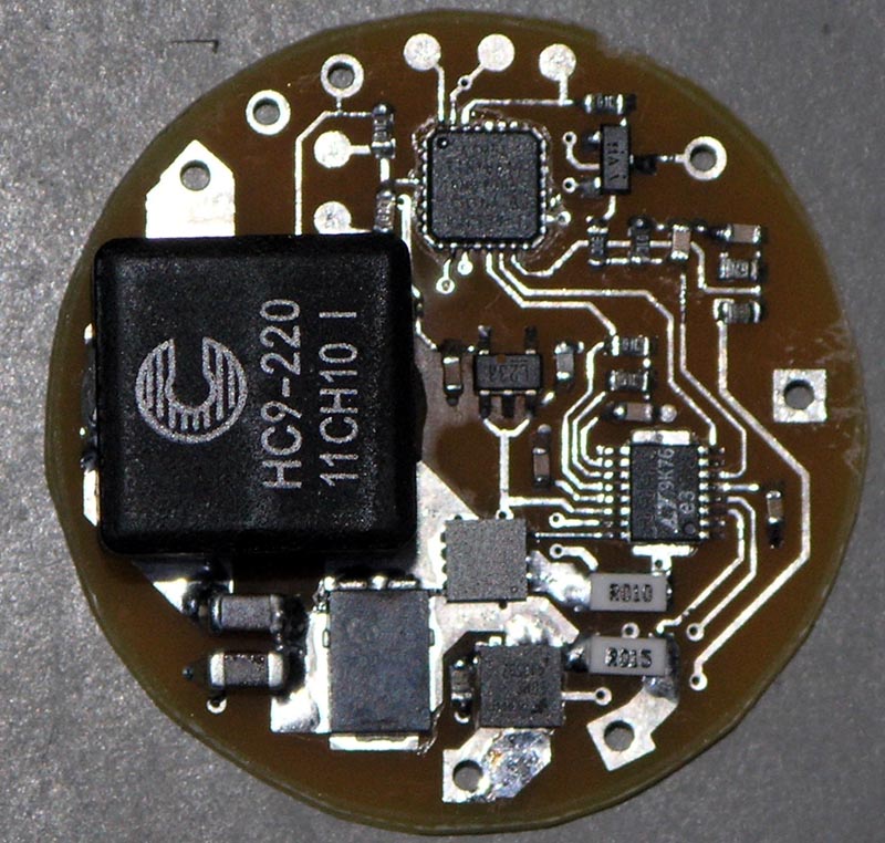
The bottom of the PCB has the thermal interface (no components) as per my other high power drivers.
cheers,
george.
Little bit of debugging to fix a few porting errors and I've got the board running on the lowest current table (1.4A). Low runs around 20mA. More testing to do to verify the standard flex features (voltage monitoring/warning, temperature monitoring etc).
First picture shows the new prototype and two jigs (top left is the test jig, top right is programming jig).
Closeup of the lastest prototype sporting the new uController. The main reason for going with the new uC (still an Atmel AVR device) was that I needed one more i/o pin and this unit provides lots of i/o's and in a smaller physical package. The extra i/o was needed to provide PWM control for reliably achieving the lowest current levels (<200mA) with decent tint control. On my previous drivers I could use a single pin for power management and PWM control, but the switcher IC I'm using on the h6flex (and h6cc, hyperboost and hyperbuck) has a dedicated PWM pin that provides some impressive control. So, now I needed one more i/o pin - so that's the story...
Bit more of a challenge to solder this tiny package, but fortunately a hot air tool and quality solder paste makes the job reasonably easy even without the soldermask of a production PCB.
The bottom of the PCB has the thermal interface (no components) as per my other high power drivers.
cheers,
george.
dan1million
Newly Enlightened
Wow H6flex is really starting to look good !
Will this have all the features of the Hipflex ?
-Dan
Will this have all the features of the Hipflex ?
-Dan
wquiles
Flashaholic
Looks awesome George - loved that close-up picture
georges80
Flashlight Enthusiast
Wow H6flex is really starting to look good !
Will this have all the features of the Hipflex ?
-Dan
Yes, it wouldn't be called a h6FLEX if it didn't have all the standard FLEX features of my drivers. i.e. it will have the exact same UI functionality, menu structure etc etc.
That imho is the one of the beauties of my flex drivers, doesn't matter whether it's a bflex,d2flex,hipflex or h6flex, the end user sees the exact same interface, nothing new to learn.
cheers,
george.
georges80
Flashlight Enthusiast
Re: H6Flex 6.6Amp Adjustable Buck - video added
Have done more testing on all current tables and all is looking good on the proto. Tested the voltage monitoring hardware and that seems to be running within 1-2% setting accuracy which is in spec.
I've taken some video that shows the driver in action on the 6.6A current table. I'm controlling the driver via a small microswitch soldered to some flying leads to the h6flex proto.
First part shows 2 parallel P7's with the h6flex set to UIP (5 levels). I'm switching through various levels from 20mA up through the levels to high (6.6A on the 6.6A table). You can see the output current on the meter (in series with the LED output).
The second part shows 3 series sets of 2xP7 (emulating a total Vf of around 11V) and doing similar tests to the first part. That's 11V x 6.6A = 72.6W running to the LEDs :devil:
I think my camcorder was screaming for some sunglasses during the test
http://www.youtube.com/watch?v=7xssW3AI1qk
cheers,
george.
wquiles
Flashaholic
Very cool video :twothumbs
georges80
Flashlight Enthusiast
I have 7 current tables implemented on the h6flex.
These are the output currents measured on the proto for the 7 tables for UIP and 5 level UIB:
L1_____L2_____L3____L4_____ L5
22mA 220mA 362mA 732mA 1430mA
22mA 280mA 534mA 1018mA 2030mA
22mA 364mA 734mA 1440mA 2825mA
22mA 477mA 932mA 1835mA 3625mA
22mA 621mA 1120mA 2364mA 5040mA
22mA 734mA 1418mA 2350mA 5654mA
22mA 818mA 1618mA 3374mA 6580mA
I've set L1 to a very low level (1 in 10 duty cycle of 200mA nominal so 20mA average). All levels above 200mA are fully current regulated (no PWM).
My thinking is a rough halving of current per drop in level, with L1 being the ultra low for extended runtime. 22mA is still quite a lot of light from a high power LED. Halving current at each level from L5 to L2 gives reasonably nice linear intensity steps, but of course that means quite a huge jump from L2 to L1. I could make the L2/L3 current steps have a larger delta to more 'even out' the jump from L2 to L1 - I'm open to suggestions.
The one thing I won't change though is UI scheme, so no programmable current values etc - the steps will be fixed based on a consensus and of course my own thoughts on the step sizes.
cheers,
george.
aurum
Enlightened
The one thing I won't change though is UI scheme, so no programmable current values
:mecry:
Similar threads
- Replies
- 4
- Views
- 3K
Latest posts
-

-
Is the 796 bulb a safe application for a reverse light?
- Latest: Hamilton Felix
-

-

-

-
