LEDobsession
Enlightened
The maximum voltage across the driver is 6V, IIRC (or something in that neighborhood, anyway). By putting the 3 LEDs after the driver, you get about 3.5V*3 = 10.5V taken care of, allowing the supply voltage to range up to 16.5V.
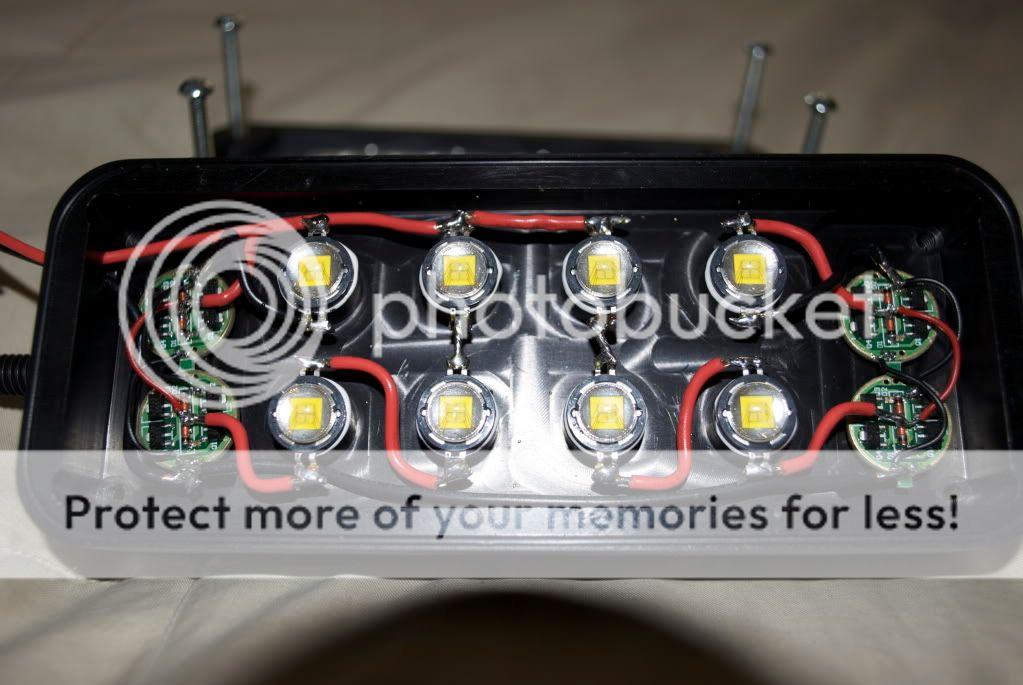
Ok that makes more sense but in those drawings (before I edited one) the 3 LEDs are before the drivers on the driver in side. So, they were connected from the battery to LEDs to driver and that just sounded to me like it wouldnt work because the driver would be limiting the current only to the LED by itself, not the 3 before. Maybe I'm just not understanding the driver in that picture very well due to it being a sandwiched driver with the 8 chips. I have been going off of that pic up above for my connecting of the drivers- its just a 3 wire connection between boards. One from center to center, one from the outer grounds with the six available holes, and one from negative to negative on the spot right above the Q2.
 .
.