HELP! 10 SSC P7 LEDs in offroad racing light

LEDobsession

Enlightened
Joined
Oct 30, 2008
Messages
507
Location
Northern Utah
The maximum voltage across the driver is 6V, IIRC (or something in that neighborhood, anyway). By putting the 3 LEDs after the driver, you get about 3.5V*3 = 10.5V taken care of, allowing the supply voltage to range up to 16.5V.

Ok that makes more sense but in those drawings (before I edited one) the 3 LEDs are before the drivers on the driver in side. So, they were connected from the battery to LEDs to driver and that just sounded to me like it wouldnt work because the driver would be limiting the current only to the LED by itself, not the 3 before. Maybe I'm just not understanding the driver in that picture very well due to it being a sandwiched driver with the 8 chips. I have been going off of that pic up above for my connecting of the drivers- its just a 3 wire connection between boards. One from center to center, one from the outer grounds with the six available holes, and one from negative to negative on the spot right above the Q2.
 

LukeA

Flashlight Enthusiast
Joined
Jun 3, 2007
Messages
4,399
Location
near Pittsburgh
Ok that makes more sense but in those drawings (before I edited one) the 3 LEDs are before the drivers on the driver in side. So, they were connected from the battery to LEDs to driver and that just sounded to me like it wouldnt work because the driver would be limiting the current only to the LED by itself, not the 3 before. Maybe I'm just not understanding the driver in that picture very well due to it being a sandwiched driver with the 8 chips. I have been going off of that pic up above for my connecting of the drivers- its just a 3 wire connection between boards. One from center to center, one from the outer grounds with the six available holes, and one from negative to negative on the spot right above the Q2.

The driver controls current for the last LED and because the LEDs are in series, the last LED controls the current for the rest of them, one of the properties of a series circuit being that all components in the series receive the same current.
 

LEDobsession

Enlightened
Joined
Oct 30, 2008
Messages
507
Location
Northern Utah
Might need optics. And it definitely needs bigger gauge across drivers. Ill mess with that tomorrow though. Now im gonna get some sleep.:tired::tired::tired:

Any recommendations for amp of fuse and relay?
 
Last edited:

LEDobsession

Enlightened
Joined
Oct 30, 2008
Messages
507
Location
Northern Utah
Larger than 18AWG?

Well I used 18 in between all the LEDs but directly between drivers I think is 22 or maybe 24. Its hard to get in those solder joints with 18 and I did it the day before and I think I was just being impatient. But anyways it turns on, it just isnt getting the right current or something. I think it will help if I rewire the boards using 18 for a start.
 

LED Boatguy

Newly Enlightened
Joined
Mar 30, 2008
Messages
102
Location
Kolleyforneah
Hey, beautiful light.

How are you mounting that rascal? Is the mount designed to be a heat path? The reason I ask is those fins probably won't keep that light cool in hot conditions. It's a beatch to work with, but a copper mount to bare metal on the quad would be best.

I make LED floodlights in the 100W+ range and use probably five times as much cooling area--and my lights typically are used in 50-60 deg F weather. Granted, I have to design for 100% passive cooling.

On the driver side, you could always gang up CAT4101 driver chips to run your strings.

Anyways, good luck.

PS Here's a good chart for wire ampacities. You want to use the Chassis Wiring column. http://www.powerstream.com/Wire_Size.htm
 
Last edited:

spencer

Enlightened
Joined
Jan 19, 2008
Messages
785
Location
Saskatoon, Canada
What are you running it off of right now? It needs about 13V or more. Ideally it would have a full 14.4V (close to cars voltage when running). Depends on the Vf of your LED's. If you are only running it off of 12 volts then it won't be running at full power.
 

LEDobsession

Enlightened
Joined
Oct 30, 2008
Messages
507
Location
Northern Utah
Hey, beautiful light.

How are you mounting that rascal? Is the mount designed to be a heat path? The reason I ask is those fins probably won't keep that light cool in hot conditions.

I make LED floodlights in the 100W+ range and use probably five times as much cooling area--and my lights typically are used in 50-60 deg F weather. Granted, I have to design for 100% passive cooling.

Anyways, good luck.

PS On the driver side, you could always gang up CAT4101 driver chips to run your strings.

The mount is not built yet. I still have some options open there. I guess Ill have to put some fins on those as well when I make them. Thanks for the information. Do you have a link to these lights? Id like to see them.

What are you running it off of right now? It needs about 13V or more. Ideally it would have a full 14.4V (close to cars voltage when running). Depends on the Vf of your LED's. If you are only running it off of 12 volts then it won't be running at full power.

Ran it off of automotive 14 vdc (truck running) last night just to see if it would work.
 

LukeA

Flashlight Enthusiast
Joined
Jun 3, 2007
Messages
4,399
Location
near Pittsburgh
The above two posts are excellent answers. The only thing I have to add is that some of the AMC drivers come preset to output 700mA, requiring a solder bridge to engage the other two chips on the board.
 

LED Boatguy

Newly Enlightened
Joined
Mar 30, 2008
Messages
102
Location
Kolleyforneah
I know it's late in the game, but could you incorporate a fan into the back of the fins? The thermal efficiency difference between passive and active cooled finned heat sinks is INSANE. I'd bet those fins would be adequate if there was a fan involved--maybe not on a 105 deg night at Glamis though :eek:.

I'd buy a fistful of DX fans, put a cheap connector on them and toss em as they clog up with dirt/sand.

PS I always put some sort of throttling mechanism (for heat) into my lights. It can be as simple as a N/C thermostat switch screwed to the light plate. If a certain temp is reached, all or some portion of the lights turn off until the temp drops.

http://www.mouser.com/catalog/637/1951.pdf Bottom of page. Make sure you get one that OPENS, i.e., Normally Closed.
 
Last edited:

Benson

Flashlight Enthusiast
Joined
Feb 15, 2009
Messages
1,145
I know it's late in the game, but could you incorporate a fan into the back of the fins? The thermal efficiency difference between passive and active cooled finned heat sinks is INSANE. I'd bet those fins would be adequate if there was a fan involved--maybe not on a 105 deg night at Glamis though :eek:.

I'd buy a fistful of DX fans, put a cheap connector on them and toss em as they clog up with dirt/sand.

A fan would certainly help when you're standing still, but I bet you get nearly as good just from airflow around it at speed, and it's got enough metal to soak up heat for short periods of standing still...
 
Last edited:

LEDobsession

Enlightened
Joined
Oct 30, 2008
Messages
507
Location
Northern Utah
The above two posts are excellent answers. The only thing I have to add is that some of the AMC drivers come preset to output 700mA, requiring a solder bridge to engage the other two chips on the board.

Where do I need to add this bridge if thats the case?

I know it's late in the game, but could you incorporate a fan into the back of the fins? The thermal efficiency difference between passive and active cooled finned heat sinks is INSANE. I'd bet those fins would be adequate if there was a fan involved--maybe not on a 105 deg night at Glamis though :eek:.

I'd buy a fistful of DX fans, put a cheap connector on them and toss em as they clog up with dirt/sand.

Thats not a bad idea. Ill check into the fans and see how I could put in some. I thought about it at some point but it just kinda faded in my excitement to finish what I knew I was doing.

A fan would certianly help when you're standing still, but I bet you get nearly as good just from airflow around it at speed, and it's got enough metal to soak up heat for short periods of standing still...

Theres definitely enough aluminum for some temporary storage. The removed fins took quite a bit of weight out but it still has a good solid mass to it. I was hoping that the movement of full speed plus the fins and aluminum material would be all the cooling I needed. I dont plan on leaving it on at a sit still for long periods of time. But yeah, Ill check out some fans.

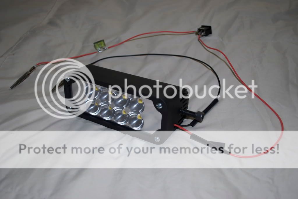
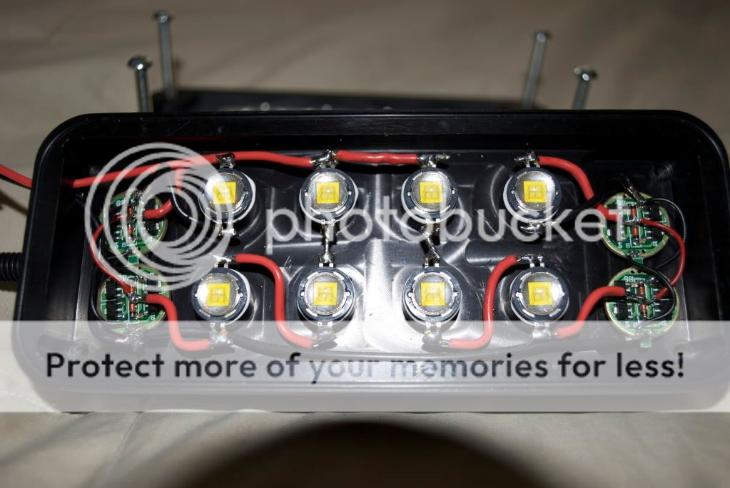
Heres the finished part and its wiring. You'll have to forgive me for the jury rigging out side the box and Im no master at the fine art of soldering either. Some joints are scary lookin but I wanted to finish so I hurried.

DSC_1296.jpg

DSC_1297.jpg

DSC_1298.jpg

DSC_1299.jpg

DSC_1301.jpg

DSC_1303.jpg
 

LED Boatguy

Newly Enlightened
Joined
Mar 30, 2008
Messages
102
Location
Kolleyforneah
Looks good. I don't see a thermal path from the driver chips to the case. Could be trouble.

On second thought re: fan--I'd nix it. There's too much bouncing and shaking going on. I'd go for a solid mounting mechanism with a good thermal path to part of the quad's structure instead.

Hell, before we overthink the thing, try running it and see how hot it gets. maybe you're fine as is. I usually let my Cree plates run 140 deg F.

One thing: On the electrical side, I usually put a 100-220uf 50V electrolytic capacitor and a .1uf MLCC 50V cap at the beginning of the circuit. The big cap (hopefully) absorbs the surges while the little guy helps with the noise.

$.02
 

LukeA

Flashlight Enthusiast
Joined
Jun 3, 2007
Messages
4,399
Location
near Pittsburgh
Looks good. I don't see a thermal path from the driver chips to the case. Could be trouble.

Those AMC chips are pretty tough and they have thermal protection built in.

That driver doesn't need anything connected, but the reverse-current protection diodes introduce a voltage drop. They can come out or be bridged to eliminate the drop.
 
Last edited:

LEDobsession

Enlightened
Joined
Oct 30, 2008
Messages
507
Location
Northern Utah
Those AMC chips are pretty tough and they have thermal protection built in.

That driver doesn't need anything connected, but the reverse-current protection diodes introduce a voltage drop. They can come out or be bridged to eliminate the drop.

So I could take the diodes completely out? What about this 700ma preset stuff? I saw this thread that talks a little bit about that but how do I do the bridge? Is it just a connection between the Q1 and Q3?
 

LEDobsession

Enlightened
Joined
Oct 30, 2008
Messages
507
Location
Northern Utah
I think I got the bridges figured out (using this) but they didnt do anything. Maybe I did them wrong. I have the same 2.59vdc (checking LED - and +) at all LEDs, but when I check from the main ground (on first board) and go around in both circuits at the 3 series LEDs, I do have a voltage drop. :shrug: I have no clue whats goin on.
 

LukeA

Flashlight Enthusiast
Joined
Jun 3, 2007
Messages
4,399
Location
near Pittsburgh
I think I got the bridges figured out (using this) but they didnt do anything. Maybe I did them wrong. I have the same 2.59vdc (checking LED - and +) at all LEDs, but when I check from the main ground (on first board) and go around in both circuits at the 3 series LEDs, I do have a voltage drop. :shrug: I have no clue whats goin on.

When I saw the pictures of your boards I didn't think you'd need the bridges.

Somewhere you're losing 4V.

What's the voltage across the alligator clips when it's running? What's the voltage across the primary positive line and primary negative line inside the unit when running? This is to try to figure out where the problem is in the circuit.

You're still testing this with your truck, right? Is the truck running when you're testing?
 

LEDobsession

Enlightened
Joined
Oct 30, 2008
Messages
507
Location
Northern Utah
When I saw the pictures of your boards I didn't think you'd need the bridges.

Somewhere you're losing 4V.

:party:
I found it. The little voltage thief turned out to be my switch. I think the bridges were needed. When I first finished this, I ran out to my truck and hooked it up. All I had was the circuit with a 30A fuse inline. It turned on but was not bright (briges were not added yet). Knowing that the whole thing worked, I ran back inside to add the alligator clips to stay on and a switch I had laying around so that I could turn it on and stand back and check out the beam. It just wasnt bright. I then heard about the possibly necessary bridges and added them. It still wasnt bright. Then, I tried checking voltages and connections. Everything was good but I for some reason missed checking between the battery and the - and + inputs on the inside of the light. I saw the drop from 14.4 at the clips and the 10.47 at the first LED but it just didnt register. Next, I checked the the in and out at the switch and that was it. Took it off and now I think its as bright as it should be. But Im thinkin that the bridges helped because the whole circuit is same now as it was at the beginning except the bridges weren't in at the beginning and now they are and... bingo.

Beam shots will be on real quick. :thumbsup:
 

spencer

Enlightened
Joined
Jan 19, 2008
Messages
785
Location
Saskatoon, Canada
If you want to still use that switch (For I don't know what reason, maybe it looks nice where you want to mount it) you can use a relay. When you turn the switch on it sends power to the relay and closes the circuit to the light. There will be no voltage drop if you use this method because the relay is designed to provide high current using a switch that isn't necessary capable of providing that load.
 
Top