Tech Tricks: Homemade Balance Charging Cradles.

DasFriek

Newly Enlightened
Joined
Jun 2, 2011
Messages
103
Whats good is the pcb seems to only be 2 layer - top and bottom, so i can see the traces of each wire. This will help verify what you stated also.
As for keeping track for now im using masking tape thats been numbered and ill label it all the way out to 7S since thats what the plug is capable of and wired for.
Ill test it on NiMH cells so i don't loose any fingers or houses during the process.
 
Last edited:

KiwiMark

Flashlight Enthusiast
Joined
Oct 19, 2008
Messages
1,731
Location
Waikato, New Zealand
Ill test it on NiMH cells so i don't loose any fingers or houses during the process.

Chances are that you will find there is no balance charge option for NiMH cells, it tends to be something that you only use on Li-ion cells. Just keep a close eye on the batteries, hit the > button to see the individual voltages and feel for signs of overheating (Li-ion cells shouldn't get hot while charging).
 

DasFriek

Newly Enlightened
Joined
Jun 2, 2011
Messages
103
Luckily my charger will charge everything i hook it too, It would charge my nipples if i ever get the urge. It does 1-16 NiMH cells at once. Its a Hyperion EOS 720i NET3 AD which is all run on software on my laptop. That is why im really wanting to get a Li-Ion setup done so i can take advantage of what the charger is made for except making graphs while testing cells. I highly recommend one if you have the extra cash to throw in the air, I don't know why i spent that much, But im glad i did.
It even has a temperature probe that shows the cells temps during cycles also.

Here is a graph of a cell from a new batch of 18350 IMR's i got from BIO.

18350cell4.jpg


Anyhow, It just so happened i have spools of red and black mono strand copper wire the same gauge as the adapters i bought for wiring up P60 drop-ins. So i didn't have to cut the adapter and the wires just slide right into the plug. But i think 7x 18650 cells is too much to count on charging at once, But its possible i may cycle all my 18350 IMR's a few times to break them in a bit as they do tend to gain capacity after a few discharges.

The wiring is a bit confusing until i pick a way im gonna attach the cells either in holders or in series with magnets with the latter sounding the easiest, But it takes up more room.
 

benckie

Newly Enlightened
Joined
Jul 1, 2011
Messages
38
Location
western australia
Mine is the same sort of thing - I'm going to keep my board intact because I have various LiPoly battery packs with the balancing leads already attached. But I've ordered some JST-XH extension leads - I figure I'll just cut the end off that I don't need and solder some ring terminals to suit my battery setup. You can get extension leads in 2-7s in packs of 10 for a few dollars from here: http://www.hobbyking.com/hobbyking/store/__9735__JST-XH_2S_Wire_Extension_20cm_10pcsbag.html

It can probably be wired up straight to the balancing plug in the charger, bypassing the board altogether.....but I'm not that smart!


they are a bit short once you get over 3s Ive been buying from here in 2s, 3s in 30cm (12 inch) and 45cm (18 inch) long approx

http://cgi.ebay.com/1-JST-JST-XH-2S...Control_Parts_Accessories&hash=item4cf84e5ee3


Maybe someone does know how to make a simple schematic from my plug so i can use it as a 7S set of leads all on its own. But if not the extension put me on the lead and idea of what i need. They show a 6S extension thats back-ordered so ill just find one somewhere else. The thing is i only need one plug as ill do it with magnets so its configurable as i need it to be.
I may pull the soft rubber backing off this board i have and look at the pin-outs and match them up to directions and pictures in the thread.
Thanks for the help.

http://cgi.ebay.com/1-JST-JST-XH-6S...Control_Parts_Accessories&hash=item4cf84e69e6

the quickest way to work it out is, the red balance wire goes on the + of the first battery and the black wire goes on the - and you group the rest, meaning the red wire from the balance plug goes on the positive of the first battery, the wire next to it goes between the negative and positive on the second battery, the wire next to that goes between the negative and positive of the third battery, you keep working your way through till you run out and the last balance wire goes on the last battery.

then you attach the main charge leads to the two out side balance wires, so the red + main charge cable goes on the the red balance wire and the negative main charge cable goes onto the last balance wire.

this is only a 2s but its the same principle

100_5210.jpg


i heat shrink the balance wires in pairs so its easy to know which ones witch.

the next one I'm making is 2 x 3s balance leads in series to make 6s with no main charge cables, but it will cost around 15 bucks to make, but it will be simple and save around 4 hours in charging.
 

DasFriek

Newly Enlightened
Joined
Jun 2, 2011
Messages
103
Wow, That explanation explained it very well! Plus the pic doesn't hurt either. Im still thinking of the best route for me to choose on layout of the cells.

And odd question, If we need to use the main positive and negative power leads, Why dont you need them with the adapter you linked above?
BTW thats a great link and i added to my watch list just in case of screw up's or i feel i need it. Thanks!
 
Last edited:

benckie

Newly Enlightened
Joined
Jul 1, 2011
Messages
38
Location
western australia
you still need them, you just have to make your own, they are just the balance wires, you cut off one end and add magnets or a Charge cradle plus your main charge leads

on another note, in my description Ive used the balance wires as black, some are blue and some are white, but the first one will be red and the last one black, but it works the same way Ive described if that makes sense,

with your Hyperion charger, leave the balance board on it as is and just buy separate balance leads you can pick any combination from 2s to 7s jst-xh leads then add your main charge cables to it, by soler or alligator clips, its the same principle of the pictures Ive posted, just my balance board is in built into the charger and yours is on the out side, then leads Ive made would plug into your balance board on your charger as they are the most common jst-xh type

the next one I'm making just waiting on the magnets will not have main charge cables to the balance wires due to they will be on a PCB and the balance wires will be the charge cables as well as balance leads, the same as attaching the main charge cables to the first and last balance wire, once its been tested ill post up pictures and link,s it should neaten up the process.
 

DasFriek

Newly Enlightened
Joined
Jun 2, 2011
Messages
103
Id really like to see pics of what your making when done, The previous work has been great and encouraged me to get off my duff and do mine like i planned on when i bought it many months ago.
The only issue about keeping the board and buying separate output cell leads is buying all the magnets and pretty much hooking them up the same way. But if i use extensions i just dont use the extra leads. So it kinda expensive to buy 6 different plug adapters and 50 magnets.

I also have green wire along with the black and red so maybe it could be helpful in remembering a hook-up sequence.
After looking at your pic above again this is pretty darn simple if you lay the cells out in a series configuration just to get used to how its done, And later if i want a more compact system ill know how the wiring goes. Using cradles and wiring that would be confusing a bit until i get the hang of it.
 

benckie

Newly Enlightened
Joined
Jul 1, 2011
Messages
38
Location
western australia
what I'm making is nothing special I'm going to use a 2 x 3s to 6s series adapter it was under 3 bucks from hobby king, i could not make one that cheap, its nothing flash just some thing cheap, easy with the xt60 plug cut off two 4mm bullet connectors added with a bit of heat shrink, then 2 x 3s balance leads with some heat shrink added to keep the balance wires in pairs with 8 cheap magnets from ebay.

i would like to use charge cradles to, easy to work out it takes a bit longer just pushes the price up a a little and just as messy but more compact, some thing like these would be good if you didn't want to make your own.

http://www.luminousdiy.com/Light%20Kits%20and%20Parts.htm#holders
 
Last edited:

DasFriek

Newly Enlightened
Joined
Jun 2, 2011
Messages
103
Well i have everything built and soldered as i already had the parts on hand as i just have been putting off making this until i learned more about the hobby and Li-Ion cells.
I think i may order one of those holders as by the time you buy small parts here and there you get the same end result but usually its not gonna look half as good as that cradle does, At least for my work anyhow.
Im gonna start with 2 NiMH AA cells that are cheapish and see how the software on my laptop responds since i control 100% of the charger threw software. After that i have many Li-Ion cells i want to cycle as capacity does go up until about the 5th cycle ive found on good cells from Sanyo and Panasonic.

If i dont respond back it means im fighting a fire and ill be online later from the library as im sure to be evicted also. lol
 

LuxLuthor

Flashaholic
Joined
Nov 5, 2005
Messages
10,654
Location
MS
Most have already answered, but you can keep the same 8 pin JST-XH connector that interfaces with your charger and say you want to charge 4s, then either ignore the extra 3 wires (stock is anticipating a need for 7s), or you can easily use a safety pin and press down on the protruding metal flange and the wire and it's plug will just slide out.

In this example, I think that is a 5s JST-XT holder with 2 empty slots since I only need 3 wires for balance charging 2 cells.

2s.jpg


They are giving you the set of plugs anticipating that you are using premade packs that have their own JST plugs that fit onto the adapter board...but you could buy a bunch of 8 pin JST-XH connectors and pins and crimpers and make your own leads.
 

benckie

Newly Enlightened
Joined
Jul 1, 2011
Messages
38
Location
western australia
i don't use the computer logveiw function of my charger I'm to lazy, but don't stress to much about fire, the flames from lipo,s only reach about 5 foot tall and about 1 wide and make pretty blue, green and yellow sparks with nasty smoke, i guess a li-ions are the same ? one of my dinning room table legs is black from a lipo years ago, long story that one.

good to see your using good cells the grey ultrafires i have pictured are not worth a pinch of kangaroo Pooh so they are the experimental cells, I'm yet to set fire to a li-ion cell, but ive melted a few leads with them and made some good sparks :huh: with parallel all in the name to save time in charging.

they seam pretty forgiving more so then lipo,s when i used to make series charge leads for balance charging multiple 11.1v 3s (3s1p) battery packs years and years ago it was easy to set them off if you didn't connect them in the right sequence.

these li-ions have been used for years in laptops and cordless power tools so they are not to bad IMO but a double check before connecting multiples together will never hurt, when i first make a charge lead for any thing i always test it on a concrete floor in the middle of my shed just in case.

I'm going to buy a back to back 6 x 18650 battery holder from the place i linked and have a go at making a pretty looking charge cradle that does not need 3 foot of space and i might even splash out and buy some decent 18650,s one day, the trust fire flames i have been using seam OK and take near on claimed mah, i was looking at some aw,s but at $18 each plus shipping :sick2:

any way let us know how you go
 

DasFriek

Newly Enlightened
Joined
Jun 2, 2011
Messages
103
Boy has this been a journey, But it seems right so im gonna go with it.

First attempt i hooked it up exactly as i was told above:

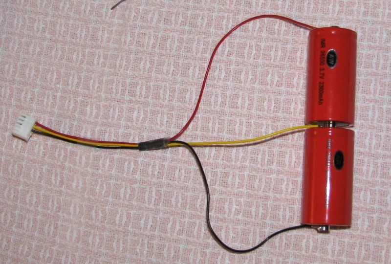
pin 1 -ve of cell 1 (main black wire also connected here)
pin 2 -ve of cell 2
pin 3 -ve of cell 3
pin 4 +ve of cell 3 (main red wire also connected here)

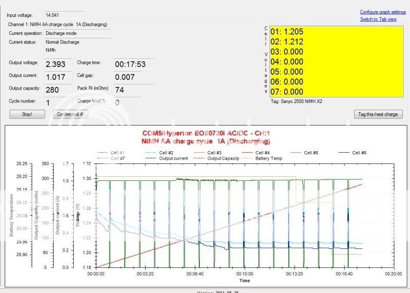
I just used 2 cells and NiMH and things were really screwy with the software, It read cell #1 at 1.3v and cell #7 at 2.6v
Of course the charger isnt gonna do anything with readings like that. So i started moving leads around as cell #7 was the issue, And that was the cell the red wire was connected to the final positive tab of the cells.
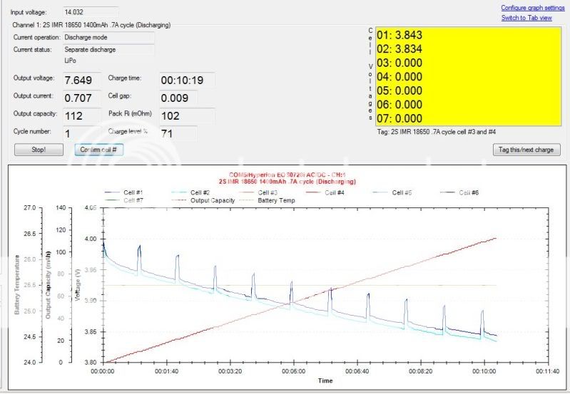
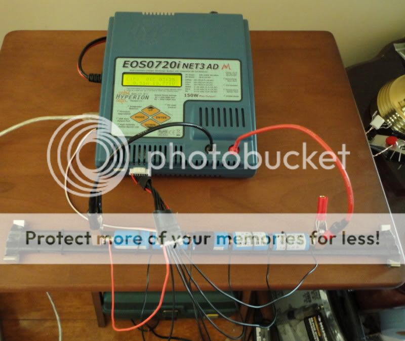
I took the red wire off and put lead #3 on there and hooked it up and it now read cell #1 @ 1.3v and cell #2 at 1.31v and was reading cell gap and performing like it should.
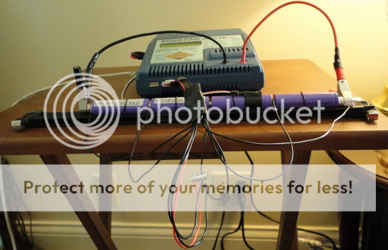
What i found also is the balance leads will read the cells and tell me if everything is hooked up correctly BEFORE i ever have to put the main power leads on.
Why my charger has to be different i have no clue, But it is.
This also explains why when i looked at the PCB board for all the differant cell count connecters plug into and it showed lead #9 (The red one) only being used with 7 cells. And the rest were wired is succession of 1,2,3,4,5(empty),6,7,8,9 (red).

So i guess from now on i start at the first negative with pin 1 and use them in order and red only gets used when i hit 7 cells.
I appreciate all the help guys as without it i would have had a clue on how to even attempt this, Let alone make an adjustment for this odd hookup.

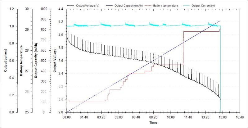
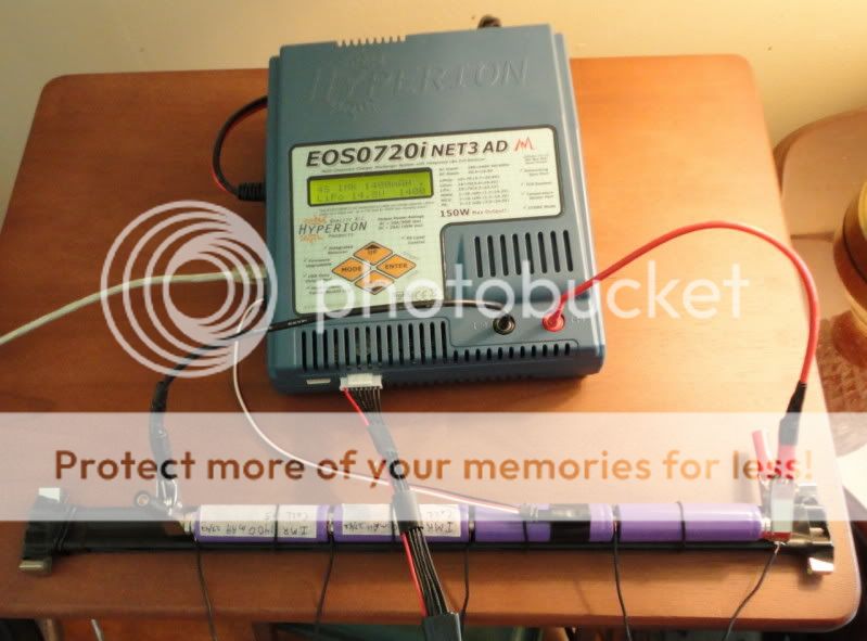
Have a look for yourselves, She's runnin great!


balancingonHyperion.jpg
 

DasFriek

Newly Enlightened
Joined
Jun 2, 2011
Messages
103
BTW on cells, I think its easier for people in the USA to get the decent cells at better prices than some people. But i try and buy a few good ones when i have spare cash and after a while i have a decent selection of high end cells.
But my first cell purchase was off ebay and i bought 4 Trustfire Flame 18650's unprotected at that and they turned out to be fakes that were relabeled as once i tested them on this charger they wouldn't hold over 200mAH capacity.
After that i swore to only buy Sanyo or Panasonic and Samsung cells, Oh and a few IMR's also. But ive been lucky as ive found a hook-up for Sanyo unprotected 2400mAH cells at $2.40 each shipped. And the IMR's from BIO are awesome except the 10440 IMR's are horrible.
 

DasFriek

Newly Enlightened
Joined
Jun 2, 2011
Messages
103
Everything ran well for the few hours while i slept cycling the 2x AA NiMH cells with balancing and peak what ever it is.
So now i went the same way in hooking up 2 IMR 18650's i just got in the mail and will run 3 cycles on them at .7/.7 charge and discharge.
As you can see everything is reading like it should and wouldn't be that way if it was hooked up incorrectly, Despite my attempts to hook it up like it should be according to the thread. So i guess it could be a cautionary tale to others coming to learn how to hook their chargers up that not everything is as it should be all the time.

Im really disliking these magnets setup as i put the cells on a ceramic saucer for fire safety reasons, But they want to move out of shape and i feel the magnets are adding some resistance as its reading high for IMR cells. i have a steel guide rail most cells will rest in perfectly, But being steel it will be a pita keeping the magnets on the cells and not the guide rail. So im really considering the flat pack from luminousdiy.

IMRbalancingonHyperion.jpg
 

KiwiMark

Flashlight Enthusiast
Joined
Oct 19, 2008
Messages
1,731
Location
Waikato, New Zealand
Im really disliking these magnets setup as i put the cells on a ceramic saucer for fire safety reasons, But they want to move out of shape

A ceramic saucer probably isn't the easiest surface to sit the cells on - I picked up a couple of ceramic floor tiles that I find work really well. They were cheap (a dollar or 2) and they are a good size, about 330mm square I think.
 

DasFriek

Newly Enlightened
Joined
Jun 2, 2011
Messages
103
I definitely agree, Its the worst thing possible. But its fire proof and im limited on space as im doing my work on my end table next to my recliner. It was fine for single cell work which was all i was doing previously.
Im working on my "Rail system" and ill post pics tonight, Its made from an adjustable sliding mount for sockets on ratchet sets. Now im insulating it since its steel and then i need to add lateral feet to stop roll over, But its perfect for sitting cells into.
But i wouldn't hurt to sit it on a tile you you suggest as the rail is thin and not much protection underneath it.


(Edit) I got the charging rail done tonight and fully insulated since its made of steel and i don't want no accidental shorts if a lead falls off a magnet. Sadly its almost unrecognizable compared to what i started with and i took no build pics as i never do, I cant take pics as my projects always change 10 times during the building process. Im waiting on 2 IMR cells to discharge and ill take pics of it all. Ill also hunt down a pic of the socket holders i used.
Here is a pic of the holders, But i used just the bare rails and put them back too back and removed the clips except to make feet on the ends with.
http://img.photobucket.com/albums/v447/deathstar13/socketholder.jpg
 
Last edited:

DasFriek

Newly Enlightened
Joined
Jun 2, 2011
Messages
103
Here is a few pics of my setup.
I wished i could have taken pics in the building process of the insulated rail, But i have a hard time doing that as my directions always change many times until i pick a final route and that would take way to many pics to make it a pita to get the work done. But basically its just 2 of the socket holder rails with the snap-on sliders removed and the rails crimped back to back using 4 of the snap-on sliders for a socket. I also added some 20mm O-rings that hold the cells in place and work great and keeping the temperature probe tight against the cell.

You will see in in the pics with the 18650 cells i had the red wire correlated to the red wire in the harness, But i switched that so i know that its the first wire to go on the first negative end in the series. The pics with the IMR 18350 shows the new wire arrangement. The charger itself is magic in how it adjusts for cell gaps while charging or discharging. It will even run until i stop it and it will keep a constant balancing job once charging is done as long as the stop button isnt hit. But it wont go over 4.201v no matter what.

Thanks for everyones help as this makes break-in cycling so much easier and 10x faster and now i get the full use of the charger i always intended to do, But didnt know how to wire it. Thanks!

DSC00649.jpg


DSC00648.jpg


DSC00651.jpg


DSC00652.jpg
 
Last edited:

My2Cents

Newly Enlightened
Joined
Apr 15, 2011
Messages
68
Location
United States
DasFriek, from what I understand, there is no such thing as "break-in" cycles for LIxx chemistry. It will actually hurt because battery loose capacity for every cycle. No way around it.
 

rmteo

Flashlight Enthusiast
Joined
Feb 11, 2009
Messages
1,071
Location
Colorado, USA
Also, since you are charging loose cells, there is no need (or advantage) to balance charge them in series - just charge them in parallel. Here's how I charge 1-8 cells at the same time.

a_66ss.jpg
 
Top