

wquiles
Flashaholic
Re: compact sst90 aspheric waterproof light build(Updated video of Hall switch workin
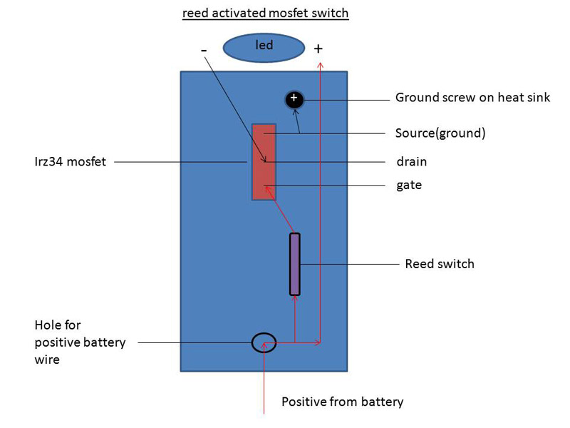
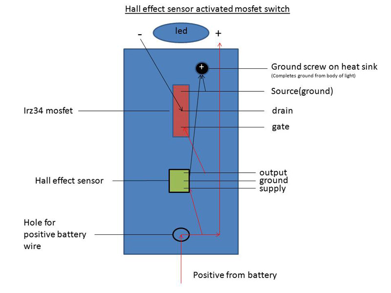
Ahh. Now with the diagram things make sense to me
According to the data sheet of the Hall switch (page 4 of 12, lower right picture for the UA package), its output pin goes LOW (to GND) when it feels the South pole within the active range, so if your MOSFET was an N-channel, which was waiting for a HIGH (Battrery +) at the GATE to turn ON, it would never turn ON. If you can let me know the exact part number of the MOSFET(s) you were trying it would be very helpful to verify this.
From your diagram it looks like you have a PNP Darlington, which makes sense it works, since it needs a LOW signal to turn ON. This Wiki page has a good explanation and pictures of the various types of bipolar and FET transistors:
http://en.wikipedia.org/wiki/Transistor
Note that although you have this setup working and it is not getting warm, the right MOSFET will have an even lower ON resistance, therefore working even better as a true switch than the Darlington (or any other bipolar) ever could.
Then again it is hard to argue with a working solution. If you test it with the highest possible current you will ever see, for extended periods of time, and it does not get too warm/hot, then consider it a good circuit and move on with the rest of the project
 Worst case is that the transistor will dissipate the same amount of power as the LED - a simple dimmer, but a very ineffcient one.