Nitecore EX10 Circuit Discussion

CM

Flashlight Enthusiast
Joined
Sep 11, 2002
Messages
3,454
Location
Mesa, AZ
Continuing the (off) topic discussion from here:

https://www.candlepowerforums.com/threads/202598

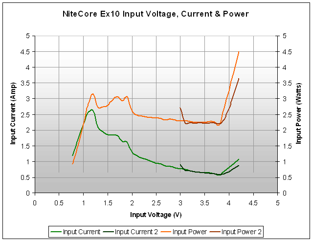
The question has been asked "What is the LED biased at?" and in pursuit of the answer, other things are revealed. I plotted the input voltage vs input current of a sample I have to determine some things about the circuit. The data is tabulated below (I will post a graph later after I upload the graphics)

Vin Iin
3.0 0.9
3.1 0.72
3.2 0.70
3.3 0.67
3.4 0.66
3.5 0.63
3.6 0.62
3.7 0.60
3.8 0.58
3.9 0.60
4.0 0.67
4.1 0.77
4.2 0.87

One thing you'll notice if you can visualize the data is that the current decreases and then increases. This tells you two things.

One is that the circuit is boost only. It is not designed for Li-Ion's as many incorrectly surmise (look at the runtime data and pictures of the light with RCR).

The statement is not conjecture, it is fact based on the data above. Having said that, it does work with RCR's for a number of reasons. At high current draw, RCR's experience enough sag that the lowered input voltage makes it appear the light is in regulation. If you were to have a low Vf LED, the light will actually run brighter initially until the cell voltage sags to the point where regulation kicks in. Above this point, the LED is in DIRECT DRIVE mode. Koala has data that shows this, and my data above also shows this.

OK, so what is the other thing this tells us? Well what's so nice about this graph is that it tells us the designed bias to the LED. How, why, where??? The plot of the data above shows an inflection point at about 3.8 volts. What's the big deal here? The current drawn from the supply at this point is the bias to the LED (on high is where I took my readings). So it appears that the LED was designed to be biased between 550mA and 600mA at the high setting. My measurements are not accurate at this point but I think it's close enough. I will take a more thorough reading later but for now, I think this answers a few burning questions about the EX10 and its circuit.

In all I'm impressed with the light. It is very high quality in many aspects and its price is difficult to beat. I have to say 4sevens and Nitecore has done a superb job in executing the design. And of course Don (McGizmo) gets credit for the PD concept that has now found its way into two commercial lights.

Cheers
 

koala

Flashlight Enthusiast
Joined
Mar 5, 2003
Messages
2,295
Location
Melbourne, Australia
Nice, good to know that my measurement is not too far off :D.

I agree after 3.8v it goes into direct drive with a bit of high khz PWM for dimming. To contribute to the data repository, I took the circuit out for the 100th time tonight :D and did some input measurements. The data is taken straight from my HP E3610A linear power supply displays. Just for fun, I hooked up the circuit and turn the voltage up slowly and for my EX10, the minimum startup input voltage is 0.78v, and it will work all the way down to 0.3v. :twothumbs

Vin Iin
0.78 1.18
0.80 1.28
0.90 1.74
1.00 2.19
1.10 2.57
1.20 2.62
1.30 2.09 (loud hum/buzzing)
1.40 1.95
1.50 1.86
1.60 1.85
1.70 1.81
1.80 1.63
1.90 1.61
2.00 1.30
2.10 1.18
2.20 1.11
2.30 1.05
2.40 1.00
2.50 0.95
2.60 0.91
2.70 0.86
2.80 0.84
2.90 0.80

Vin Iin
3.00 0.76
3.10 0.74
3.20 0.71
3.30 0.68
3.40 0.66
3.50 0.64
3.60 0.63
3.70 0.61
3.80 0.57
3.90 0.69
4.00 0.81
4.10 0.94
4.20 1.07
 
Last edited:

UnknownVT

Flashlight Enthusiast
Joined
Dec 27, 2002
Messages
3,671
If you were to have a low Vf LED, the light will actually run brighter initially until the cell voltage sags to the point where regulation kicks in. Above this point, the LED is in DIRECT DRIVE mode. Koala has data that shows this, and my data above also shows this.

Many thanks for this -
if the LED is in Direct Drive at battery voltages above Vf -
is the boost circuit in effect by-passed?
how does the EX10 achieve its lower brightness levels?

is it as koala says -
I agree after 3.8v it goes into direct drive with a bit of high khz PWM for dimming.

Are the lower levels achieved by high kHz PWM?
 

ViReN

Flashlight Enthusiast
Joined
Apr 3, 2004
Messages
3,078
Location
CPFReviews.com
NitecoreEx10.gif


Just a chart drawn from above data to assist the understanding. To me it appears that circuit is best designed 2.4 to 3.7 V
 
Last edited:

kurni

Enlightened
Joined
Aug 7, 2006
Messages
529
Location
Sydney, Australia
Ouch!!! I don't like the look of Pin above 3.8V. It might not damage the LED but am I right in guessing that efficiency is down the drain?
 

CM

Flashlight Enthusiast
Joined
Sep 11, 2002
Messages
3,454
Location
Mesa, AZ
Just a chart drawn from above data to assist the understanding. To me it appears that circuit is best designed 2.4 to 3.7 V

Thanks for plotting our data ViRen. There is one important thing to note. Both data sets show an inflection point at around 3.7-3.8V and the minimum of the two curves roughly coincide between 550mA and 600mA. This is the Iout that most of you are probably interested in.


Thanks for the data guys. Did anyone measure Iout?

That's the beauty of doing a characterization like above. Iout is roughly 550mA to 600mA.


So, for you electronic whizzes out there, quiz time. What should the curve look like for

a) Buck circuit
b) Buck-Boost circuit.

Sorry but the only prize I can offer is your notoriety as an electronics whiz :nana:
 
Last edited:

ViReN

Flashlight Enthusiast
Joined
Apr 3, 2004
Messages
3,078
Location
CPFReviews.com
CM,

It's definitely not a pure buck circuit, as you can see, the light operates at lower voltages (well below Vf of LED) ... also the shoot out of current after 3.7 V makes me believe that it's a simple boost circuit. I could be totally wrong though.
 
Last edited:

CM

Flashlight Enthusiast
Joined
Sep 11, 2002
Messages
3,454
Location
Mesa, AZ
CM,

It's definitely not a pure buck circuit, as you can see, the light operates at lower voltages (well below Vf of LED) ... also the shoot out of current after 3.7 V makes me believe that it's a simple boost circuit. I could be totally wrong though.

From my first post, it is boost only:

...One is that the circuit is boost only...

But no one has taken up the challenge to take a shot at my two questions above about what the shape of the other type of circuits ;)
 

MorePower

Enlightened
Joined
Nov 4, 2006
Messages
643
Location
Wisconsin
So, for you electronic whizzes out there, quiz time. What should the curve look like for

a) Buck circuit
b) Buck-Boost circuit.

Sorry but the only prize I can offer is your notoriety as an electronics whiz :nana:

Well, for a buck circuit, if you plot the data Drewfus2101 posted in this thread on the DX sku.6090 then you'll have your answer for that question...
 

Bullzeyebill

Flashaholic
Joined
Feb 21, 2003
Messages
12,164
Location
CA
Yes, PWM at 37kHz.
Perhaps you will find some of my posts in the thread "EX10 (1xCR123A) and D10 (1xAA) Part 5" interesting: #104, #108, #119, [URL="https://www.candlepowerforums.com/posts/2553728&postcount=1[/URL]

I can see you are not surprised by the conclusions that have been drawn in this thread. Good work on PWM explanation.

Bill
 

Tohuwabohu

Newly Enlightened
Joined
May 8, 2008
Messages
184
Location
Germany
I can see you are not surprised by the conclusions that have been drawn in this thread.
That's right. But I have to admit that owing an USB-scope gave me a huge advantage. I did not have to draw any conclusions, I coud actually see the boost circuit start working as the voltage of the battery dropped.
Good work on PWM explanation.
Thanks. I hope I did not get it to wrong. I still have to learn a lot about flashlight electronics.
 

CM

Flashlight Enthusiast
Joined
Sep 11, 2002
Messages
3,454
Location
Mesa, AZ
Just finished boosting the circuit from 570 ma to about 850mA on high. It's not a whole lot brighter (no surprise there) unless compared to a known light. Lux increased about 40% from stock bias. Gets hot faster so I'm not sure I like it this way but for short runs it should be good to go.

Hmmm, does that mean I need to start another thread in the home-made and modified?
 
Last edited:

toneloe

Newly Enlightened
Joined
Nov 5, 2002
Messages
41
Location
houston
It's the 0.15 ohm resistor that sets the current I already figured that out. However, the stock bias is where *I* would like mine to be set. However, I realize there are those that want balls to the walls and the 0.15 ohm resistor needs to be decreased to say 0.1 ohms or so.

Did you get the 850mA by changing the 0.15 to 0.1 or did you use a different value.
 

CM

Flashlight Enthusiast
Joined
Sep 11, 2002
Messages
3,454
Location
Mesa, AZ
Did you get the 850mA by changing the 0.15 to 0.1 or did you use a different value.

Yes, 0.1 ohms.

I have to say that my initial impressions about the output have changed. I used it for two nights now and compared to another stock EX10 it is noticeably brighter in real world use. For the size of the light, it is very impressive. While it doesn't compare to the Arc6 (which incidentally is a $300 light) in output and tint , I'm still amazed at its price/performance point. I will have to try another resistor to see if I can make it approach the Arc6 output.
 

toneloe

Newly Enlightened
Joined
Nov 5, 2002
Messages
41
Location
houston
Let me know how that work out and what value you use, I notice only a slight gain in output with the .1
 
Top