3D printed 18650 light, playing with the idea

PeterFH

Newly Enlightened
Joined
Sep 23, 2016
Messages
60
Hello!
Quite some time ago i sparked the idea to build a flashlight, it is a few months later now and i have a rough idea on how to do it.
In my parts bin are about ten 18650 cells, 20 LED drivers, a few Nichia LEDs and a 3D printer, all that needs to be put to good use.
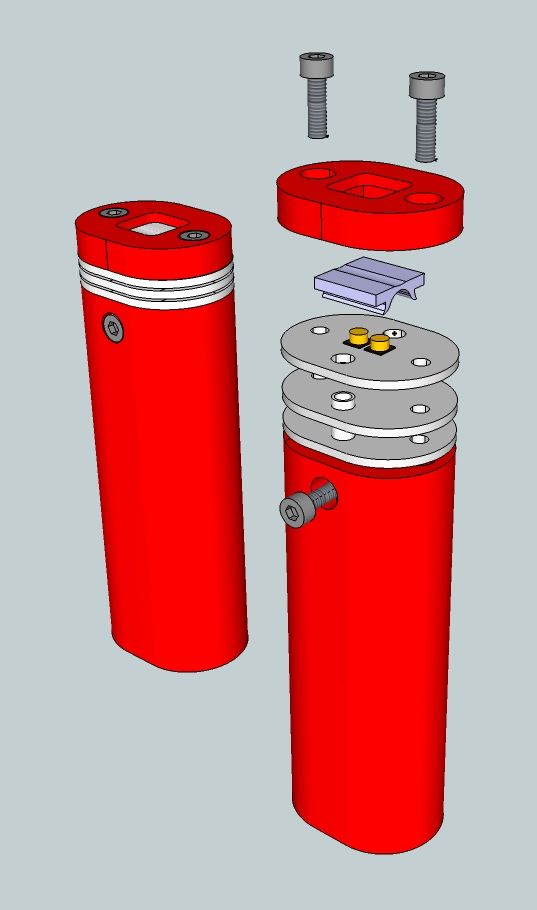
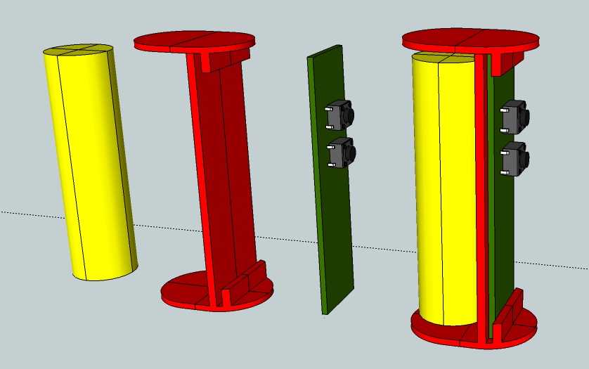
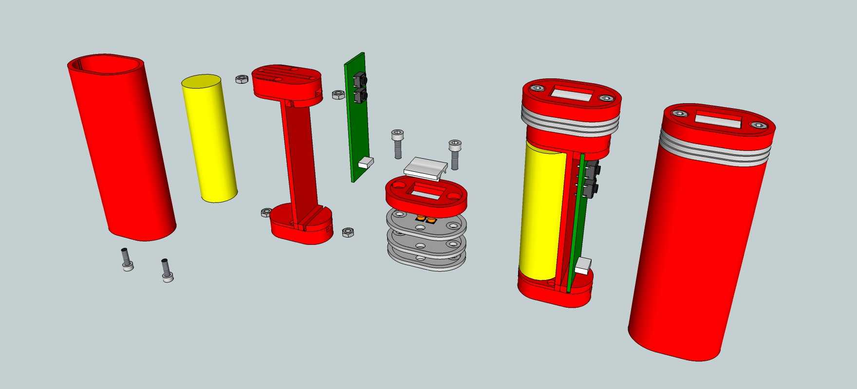
So i am set on these four things, here is what i came up with so far, just made some prints to have something in my hand to play with:

http://imgur.com/qankruB

What i know so far, a 3D printed case seems to be viable (if printed in PETG), heat dissipation of the LED will be a problem, 18650 makes the light a bit too big then i would like to but i do not want to buy new batteries.


LED options:
Nichia NF2L385AR,170 Lumen, 2700K with 83RA
Nichia NF2W385AR,197 Lumen, 5000K with 83RA
Cree MK-R, 350 Lumen, 2700K with 80RA
I am unsure about a lens, either a whide angle or none at all, i want a floodlight.
If possible i want to put a temp sensor in there so the light can regulate the power down if it gets too hot, just a cheap NTC/Resistor solution.


LED Driver with no PWM
Texas Instruments TPS61165,i have 20 of them and they fit the LED nicely.
It has a digital interface and can regulate the current in 31 steps.
With a max LED current of 250mA it gives a resolution of 8mA per step and so the lowest light output is 8mA at roughly 6V.
Since it does not use PWM the main controller can go to sleep once the current is set.


USB rechargable with build in charger
Microchip MCP73833, i still have some of them as well.
It provides a thermal cutoff while charging if the cell gets too hot with a NTC and it has 3 pin status output.
Not too expensive and i really like the 3 pin output.
It indicates "power good", "charging", "full" and "fault" with 4 different states instead of just a light that goes on and of.


User interface
Two buttons for power up/down and on/off or whatever idea i got, i do not want a single button.
One RGB charge indicator LED.
One dual color battery level indicator with rough battery level aproximation through cell voltage.
I never tried that and guesstimating the charge of a Li* cell by the voltage alone is not a good idea but it is all i can do with the selected components.
As a controller i have chosen the ATTiny85 because they are cheap, i want a bit more flash then a ATTiny13A and everything else is too expensive and big.


Other things
The cell needs to have a second protection circuit, i am toying with the idea of a Texas Instruments BQ29700 cell protection IC, it is fairly cheap but i hate soldering compoents without legs and this thing is tiny.

The whole, how will i mount and cool the LED is still a bit problematic but solveable.
The electronics should be fairly cheap, all on one PCB with all components on one side except the switches, if possible.
I may have to mount the switches and LEDs on the backside, i only work with 0805 SMD parts and hate leg-less packages, so i am stuck with bigger components.
With 0603 and QFN packages everything would fit on one side.


That is about it, what to you guys think?
 
Last edited:

DrafterDan

Flashlight Enthusiast
Joined
Jul 28, 2013
Messages
1,317
Location
Phoenix, AZ
so you're planning on the extra components being alongside the battery? It's an interesting configuration. If you are running about 350 lumens, then the heat load won't be too great, however the largest aluminum/ brass/ copper heatsink you can get to fit will always be a good idea.

View attachment 4337

What are you doing for a reflector? How are the head/ tail attached to the body?
 

PeterFH

Newly Enlightened
Joined
Sep 23, 2016
Messages
60
DrafterDan;5023767 said:
so you're planning on the extra components being alongside the battery?

It is the only way that makes sense to me in this case, yes.
Makes the buttons way simpler to mount and i have a bunch of room for all the components i want.

What are you doing for a reflector?

That is indeed a problem, i can not find one that i like and even then i have a problem that i need to cover it up.
To make it easy i am leaning towards a 10mm lens with a 38° beam angle (Carclo 10773) that should work with the LED and the case.

How are the head/ tail attached to the body?

Got rough ideas but nothing solid, i think i want to glue them together, maybe screws but i am unsure.
I do not like the idea of a glued case but i want it to be somewhat waterproof and compact.
 

PeterFH

Newly Enlightened
Joined
Sep 23, 2016
Messages
60
I think i came up with a semi-decent solution that should work:

http://i.imgur.com/OFcwDGC.jpg

Since the PCBs are damn cheap i can just use two and put two spacers between them and screw the whole sandwich together.
The spacers are easily made since they are just two aluminium tubes, maybe i can even glue them together with thermal adhesive.
 

PeterFH

Newly Enlightened
Joined
Sep 23, 2016
Messages
60
Thanks for the reply!
I do want it to be... lets say... rain proof.

So, nooks and crannies were dirt and water can get in, the usb port i want to seal up with a small plug with a o-ring.
 

PeterFH

Newly Enlightened
Joined
Sep 23, 2016
Messages
60
This seems to be a viable solution, it is not pretty but gets the idea across.
I upgraded to two Nichia LEDs, they get to around 394 Lumen for cold white and 338 Lumen for warm white at max current.
This perticular type is used because i can get them for only 79 cents a piece and they run at 129 and 159 lumen per watt efficiency at 100mA.
Those are pretty good numbers for the price it think.

Ivhi11U.png


This still is a very odd combination of parts and LEDs used but the idea is odd in general.
Since the metal core PCBs are rather cheap i can just use 3 of them, one has the LEDs on it, the others just serve as a heatsink, if that is not enough i can just stack more PCBs for more surface area.
Everything sandwiched together with spacers and M3 screws, M3 since i use them everywere in my projects allready.

The cables for the LEDs go through two small aluminium tubes that to through the stack, they serve as alignment pins as well.

There is no optic, this is very intenionally a flood light, the "lens" i plan to use is from a LED strip cover.
A mock up with some duct tape and my bench supply and the two LEDs that i have showed that the beam looks nice that way, it looses a bit of brightnes but finding a proper optic for this was not easy.
 

PeterFH

Newly Enlightened
Joined
Sep 23, 2016
Messages
60
The head is mostly sorted out, the next step is trying to fit everything else together.
This is a very rough sketch on how the internals are held together, i just wanted to shove everything into a tube and slather it in hot glue but i want it to be pretty on the inside as well.
There is not a big chance that i will be able to get away with those buttons, most likely i will have to use low profile ones.
That means i got to figure out how to mount buttons caps on the thing.

I mainly have to figure out the rough size of the PCB and how to mount it.
Then route the whole thing so i can model the body and button caps for the PCB.
The main issue is, how i get the USB plug poking out somewere at the bottom.

Since i want to use screws in the base it will be a bit thick...

Wjt0aM2.jpg
 

PeterFH

Newly Enlightened
Joined
Sep 23, 2016
Messages
60
Slow and steady progress, before i can finalise all the dimensions i got to figure out how to do the switches and cover for the micro usb connector.

XDOJjzq.jpg
 

DrafterDan

Flashlight Enthusiast
Joined
Jul 28, 2013
Messages
1,317
Location
Phoenix, AZ
You might consider a thicker heat sink for your two LEDs. Especially in a plastic body, it will be difficult to draw head away from the head.
I like how this is progressing!
 

PeterFH

Newly Enlightened
Joined
Sep 23, 2016
Messages
60
You might consider a thicker heat sink for your two LEDs.
I like how this is progressing!

Thanks!
The grey parts are aluminium, that should be enough cooling for the LEDs to stay at a comfy temperature.
 

PeterH

Newly Enlightened
Joined
Aug 31, 2010
Messages
52
How much power are you planning to feed the LED with that tiny heat sink?
 

PeterFH

Newly Enlightened
Joined
Sep 23, 2016
Messages
60
How much power are you planning to feed the LED with that tiny heat sink?

About 3W max, i have the LEDs allready sitting on my desk on smaller heatsinks.
They work allright, they should have a substantially bigger surface area on the custom PCBs.

But, there will be a thermistor on the PCB as well, if it does get too hot, the controller can turn down the power.
 

PeterFH

Newly Enlightened
Joined
Sep 23, 2016
Messages
60
Now that i got a rough idea how much space i got for the PCB i want to make sure the electronics even work properly before i print parts.
A bit of late night tinkering, most likely with a bunch of mistakes…


Here is a first draft of the schematic:
http://i.imgur.com/dZj5LCs.jpg


Charger, LED driver and Battery protection, it looks like i might have to use a ATTiny84 instead of a ATTiny85.
The lack of pins that leads to compromises does not sit too well with me.
The 6 more pins i can put to good use.
 

PeterFH

Newly Enlightened
Joined
Sep 23, 2016
Messages
60
In case someone is still interested...

Slowly it starts to look like it might work, here is a picture:

http://i.imgur.com/jUMHXyS.jpg

I think i have all the signals i need now, looked at the price for the processors and what i still have.
Since i have the room for one and it costs just 2 bucks more, i just went with a arduino compatible ATmega328p.
Got a few left over as well, i might add a crystal and route out the UART, i will see.

I want to route the board from the final schematic, that spares me one possibility to **** up before i order a few boards from china.
Gonna sleep a bit on that...
 
Last edited:

PeterFH

Newly Enlightened
Joined
Sep 23, 2016
Messages
60
Mh, the schematic seems to be complete so far, only a pin header is still missing:
http://i.imgur.com/7yUQaLA.png

And some rough shuffling of components on the board:
http://i.imgur.com/8LJJMQo.png

That is, of course, way bigger then the final product, it makes no sense to make it small at this point.
That just asks for trouble and since i etch these at home, it does not matter.
 

PeterFH

Newly Enlightened
Joined
Sep 23, 2016
Messages
60
In case someone is still interested, not much has happened yet, i routed the board and i think i finalized the schematic.
Most likely the 3rd button and the 3rd status LED will get axed but for now they serve a handy purpose.

The processor is way too big but it is common and cheap, id like to have a I2C interface for some other things i might want to do with the thing:
http://imgur.com/AvrbwQk

Here is the board, way too big, not shown the ground pours on the bottom and top layer.
The bottom is one solid ground plane, hat to put in 3 jumpers on the top layer, the routing is not the best but if should do for now:
http://imgur.com/0k572rC
 

PeterFH

Newly Enlightened
Joined
Sep 23, 2016
Messages
60
Things are still progressing, tossed everything into the bin and started over, too big and complicated for a start.
I found two lonely ATTiny26 in my parts bin and wanted to use those, then i got frustrated at coding in C and wanted to switch back to the Arduino IDE, i got a few AtTiny44 for a few bucks on Ebay, they should work nicely.

Layout done, printed and roughly test fitted with parts.
It has the exact dimensions of the battery holder i had left over and want to use to get started:

http://imgur.com/zGMmvm0

The charging and cell protection will be done by one of these china modules, i wanted to play with them anyway.
After i got the parts from TI i was reminded how small these WSON packages are and i am not in the mood to deal with that at the moment.

There are a few components missing, i do not have suitable output capacitors for the regulator.
Only got 10V and i need 25V, to be precise, it should be 50V ones but they are pricey in low quantities.

And all the inductors i have are too small...

The parts should arrive Tuesday and Wednesday i should know if this really works.
 

PeterFH

Newly Enlightened
Joined
Sep 23, 2016
Messages
60
I etched a few PCBs, it is a bit of a gamble but the only part that i have not checked to footprint of is the inductor, i just hope it will fit:

http://i.imgur.com/cUiDc3A.jpg?2

I will put all the parts i have on them and start writing a bit of code, there will be at least a few blinky LEDs today, i hope.
 
Top