3rd_shift
Flashlight Enthusiast
I finally got this one done.
Now wouldn't it be nice to have a bright and white flashlight as bright as a 60 watt housebulb that runs good on regular unleaded batteries? :wow:
The technology is here at last to put one together thanks to Cree and Seoul Semiconductor.")
So let's get some tools out and have some fun.
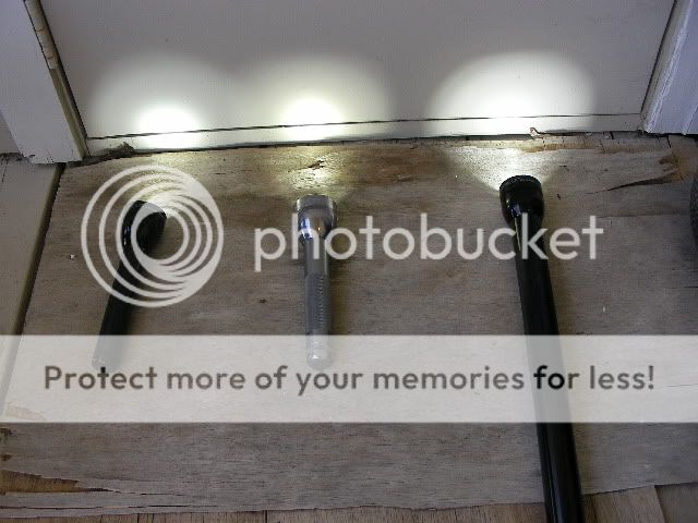
Here we have a 2C and a big 6D.
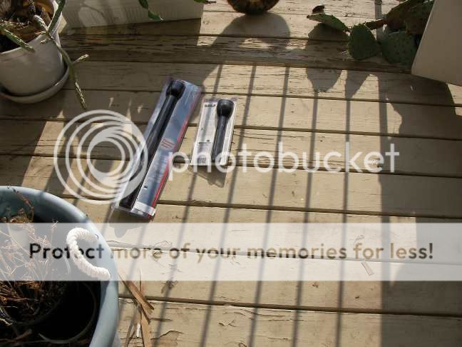
You may use any Size maglite as long as the power source is around 7.5 - 9 volts as these flashlights will have.
For example, a 2D with 2 lithium ion batteries, or 6AA's in it will also work.
Or a 6c with regular c cell batteries should also be just fine.
Both of these will have thier Led stars series parallel wired for this one.
You may also go for an all parallel setup using a 3C, or 3D light instead based on this pictorial modding adventure I did.
Here is a video showing the disassembly of the two lights.
Broadband internet connection is recommended, and the video will automatically play as soon as you click the link.
If it won't play, grab the newest version of flash player with a google search.
http://smg.photobucket.com/albums/v313/3rd_shift/?action=view¤t=SANY0003.MP4.flv
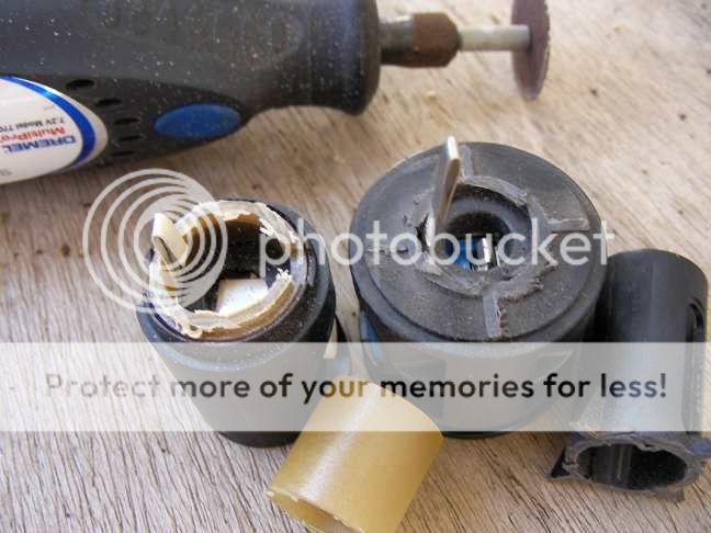
Here is another video showing disassembly of an older pre 2001 C cell Maglite.
http://smg.photobucket.com/albums/v313/3rd_shift/?action=view¤t=SANY0088.MP4.flv
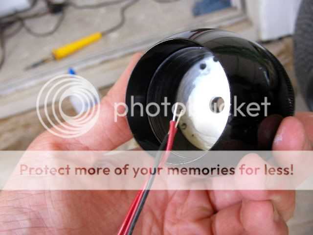
Here are the bulb holder guts removed with a 5/64rths allen wrench.
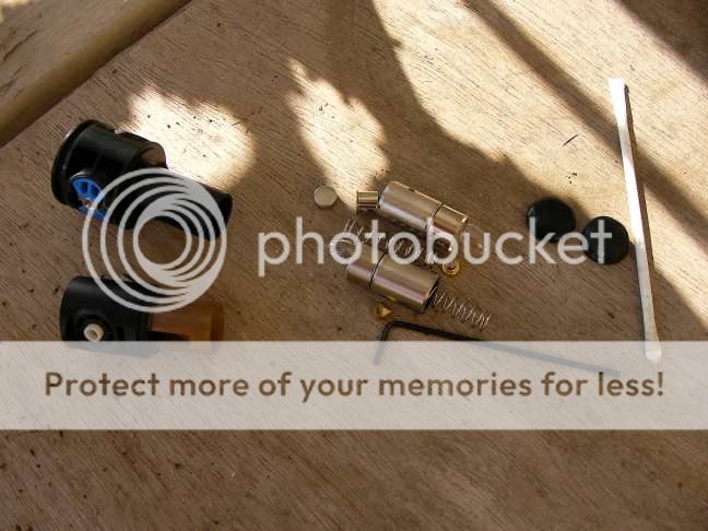
Make the bulb assemblies look something like this.
The head needs to be secured so that it won't turn anymore and tear up the wiring inside. :mecry:
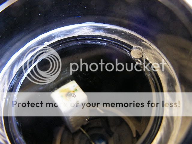
Drill an 1/8 hole about a quarter to a half inch in like this and put a metal plug in there that sits flush,
or slightly below the top of the hole once inside.
This will jam the threads and stop the head from turning anymore.
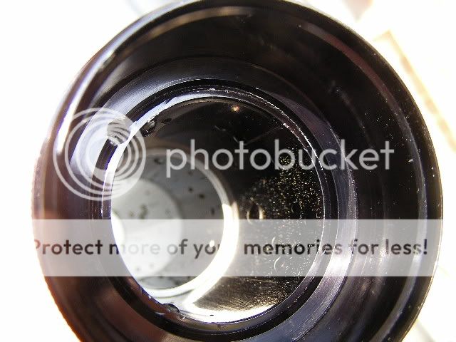
A 2D was used to demonstrate this step, but this works with all C/D Maglites that I know of.
Here is another picture with the head removed again.
This next segment is for the D cell
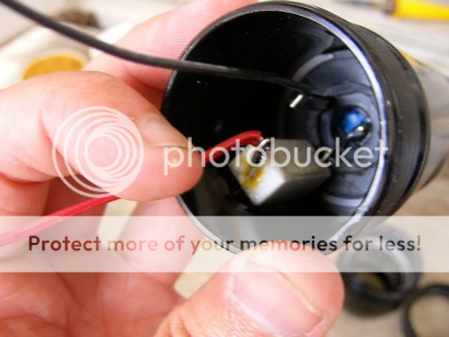
For the D cell, install 4 inch long wires, 2 red (+) and one black (-).
The resistor in the picture is a 5 watt rated 1 ohm.
Re-install the wired switch assembly like this.
Here is a video showing how the resistor was secured.
http://smg.photobucket.com/albums/v313/3rd_shift/?action=view¤t=SANY0023.flv
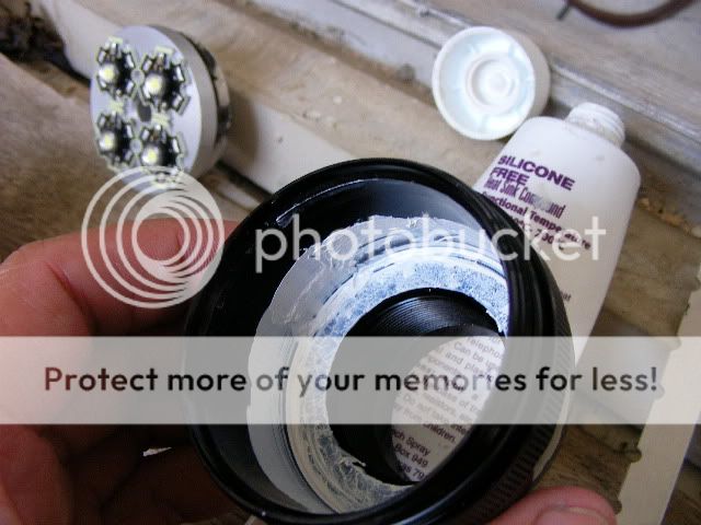
Put in a D cell starsink (5mm thick) for so17 minireflectors, but use khatoid 17mm's instead with thier bottoms widened out for Cree XRE leds.
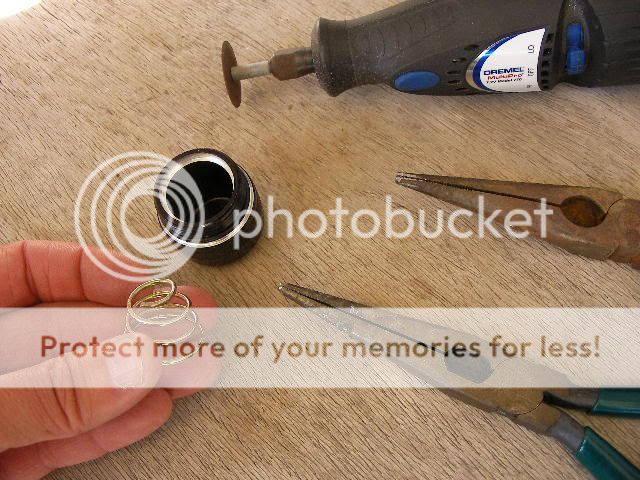
Khatoid reflectors bottoms can be widened out with a small, narrow knife, or one of the blades of a small pair of sharp scissors as I did.
Just make sure it is bullseye centered over the led after it's bottom is big enough to fit.
Try to keep fingerprints and any sharp objects clear of the insides of the reflectors.
Put thermal grease under the heatsink before putting it in.
Here is a video of that part of the assembly.
http://smg.photobucket.com/albums/v313/3rd_shift/?action=view¤t=SANY0026.flv
Q4 strength in this case at over 100 lumens at 350 milliamps.
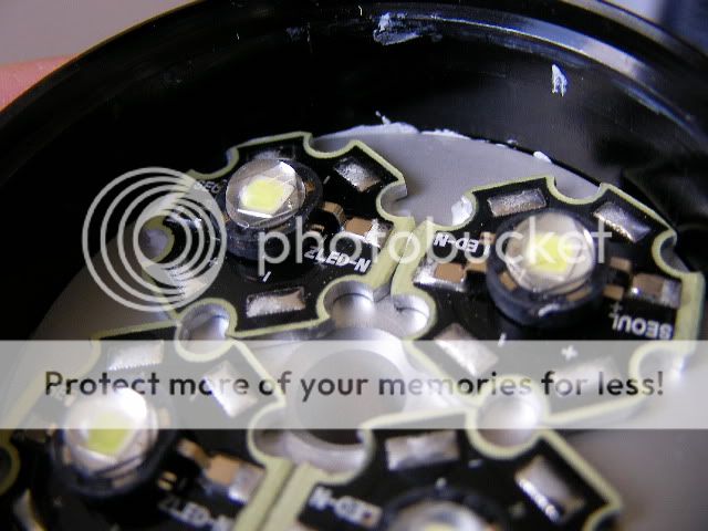
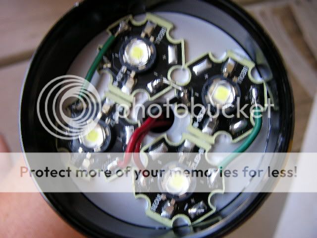
File off thier sharpest edges until they all fit inside like this.
There is a choice here on whether to use thermal grease, or arctic alumina adhesive.
I used thermal grease under the Cree XRE stars in this case, and then wired them up just like so.
The (-) sides of the stars are nearest the wire inlet hole in the heatsink.
Load in some batteries with the tailcap off and try it out with a dc ampmeter and cross your fingers. :duck:
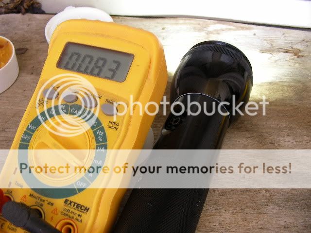
830 milliamps on some old batteries is quite nice and comfy as the leds are only seeing about 415 milliamps each.
With fresh batteries, this light tops out at 1.1 amps which is still not driving them too hard. More than 1.5 amps is hitting them kinda hard.
We're aiming for relliability and runtime for this one this time around.
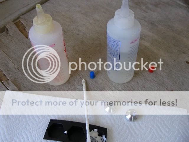
Now let's make a mess to hold those reflectors still with.
I used black silicone gasket maker for this.
One may use whatever desired to keep the reflectors planted and centered with.
Give that some time to cure.
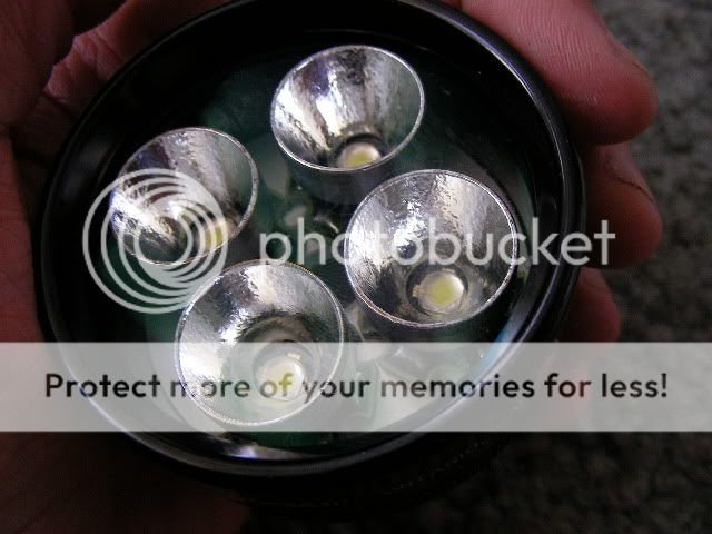
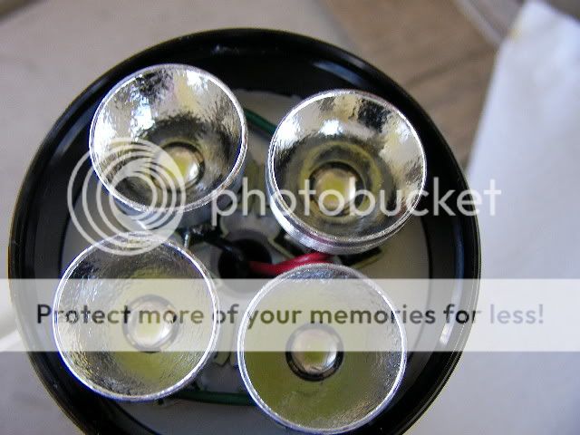
Here is a picture of the completed business end.
A little of that black stuff did ooze in, but is still out of reach of the relatively narrow beam angle of the leds.
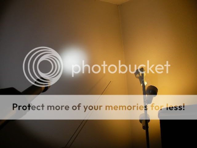
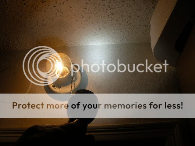
Here it is embarrassing a 60 watt vanity bulb. :laughing:
Now to tackle the C cell
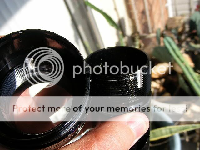
Find and cut some 5/8ths heater hose from the local auto parts store and cut it to 4.5-5 inches in length, then slit it down one side.
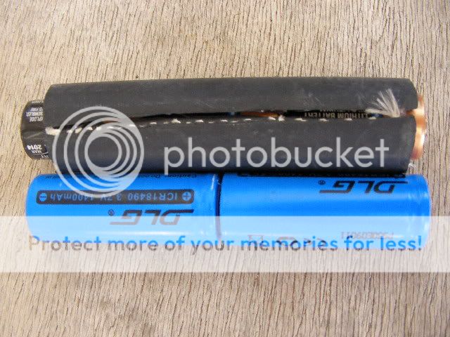
3 cr123 batteries, or 2 18500 lithium ion batteries and charger from member AW in the dealers corner at cpf marketplace will also do.
Now cut and reshape the tailspring about a quarter inch shorter so it won't squash the batteries quite so hard.
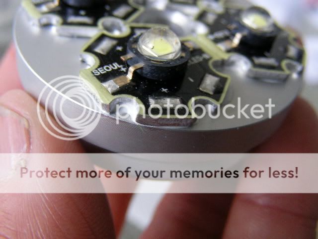
File, or lightly grind off the sharpest edges off of some SSC P4 led stars.
An adjustable heatsink from member download is used this time.
Mount and glue the stars with thier (-) closest to the center hole with arctic alumina.
Let that cure.
Then file, or shave off any overhanging edges from the stars so that the heatsink can drop right in.
We need to find out what height to adjust the heatsink to.
Put some heatsink grease into it's threads to improve thermal contact between the 2 pieces of the heatsink.
Here is a video of it being adjusted in another, but older pre-2001 2c Maglite.
Even I'm still a bit new to this.
http://smg.photobucket.com/albums/v313/3rd_shift/?action=view¤t=SANY0089.MP4.flv
Loosely assemble everything like this and adjust the heatsink height until everything fits ok.
Be careful not to damage or destroy the fragile gelatin domes from doing this.
Some older obsolete luxeon1 stars can be used instead for this step if preferred.
Once that's done and everything fits good in the Maglite head, we need to stop the heatsink from turning any more.
I used blobs of silicone gasket maker for this and let it cure.
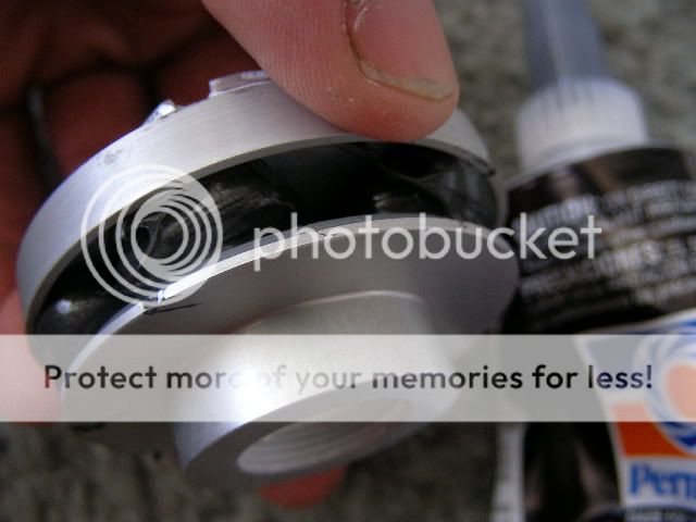
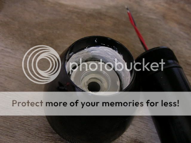
Now apply plenty of heatsink grease at the bottom of the Maglite head, it's threads and the sides inside for best possible thermal contact and conductivity from the heatsink's bottom and top pieces.
Perfect. There is heatsink grease there to catch and transfer heat from the top piece of the 2 piece adjustable heatsink assembly.
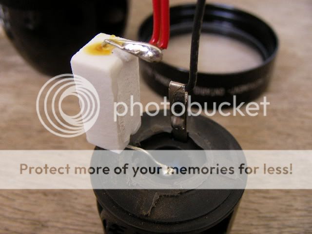
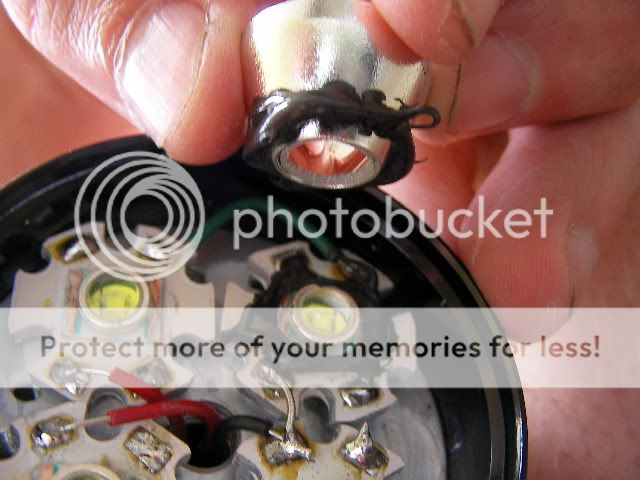
Reinstall the wired switch assembly (see the D cell assembly for more on this) with your 5/64ths allen wrench and arctic alumina a 2 watt rated 1.5 ohm resistor just like so.
The two 4-5 inch long red (+) wires are coming from it.
It's other end is soldered to the center tab contact of the switch assembly.
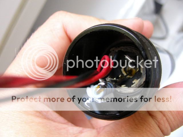
Too much heatsink grease just isn't enough is it? :laughing:
Here is a blurry photo of the C cell's wiring. :huh2:
See the D cell assembly for a clearer picture of the same series parallel wiring, my bad.
Load in some batteries and try it out with a dc ampmeter.
This one pulls about 1.2 amps from 2 lithium ion 18500 batteries.
This is a healthy power draw for this light with these leds at 600 milliamps per led.
This light is close to 600 lumens and can still be left on for quite a while without getting too hot. :twothumbs
This next step is a good idea to keep those metal 17mm reflectors from sliding around and scraping off the soft gel domes from the SSC P4 leds. :green:
Regular 2 part epoxy was used in this case.
Apply it to the tops of the emitter flanges without it getting onto the domes themselves.
Then apply it to the bottoms of the reflectors and set them down on top of the led shoulders and "bullseye" center them as you do.
Let it cure hard 1st with the flashlight standing straight up.
Do not install the bezel yet.
If some excess runs down onto the stars, that is actually good.
We want that to happen in this case for a good adhesive grip to hold the reflectors still and centered when the bezel is put back on later.
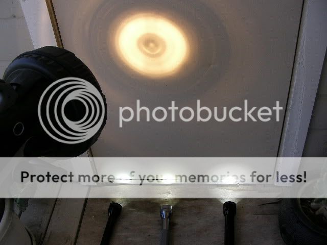
Beamshots! :naughty:
Here it is also embarrassing a 60 watt vanity bulb.
On the right is the 6D 4x Cree XRE at 9 volts x 1.1 amps.
Center is a 2c MiniMonsterQuad with 4 WWOT Luxeon5 leds at 7.5 volts x 3.5 amps.
Left is the 2c 4X USWOH SSC P4 led at 7.5 volts X 1.2 amps.
Same lights versus a Thor 15 million candlepower rated cordless gelcell spotlight.
Happy modding! :thumbsup:
Now wouldn't it be nice to have a bright and white flashlight as bright as a 60 watt housebulb that runs good on regular unleaded batteries? :wow:
The technology is here at last to put one together thanks to Cree and Seoul Semiconductor.
So let's get some tools out and have some fun.
Here we have a 2C and a big 6D.
You may use any Size maglite as long as the power source is around 7.5 - 9 volts as these flashlights will have.
For example, a 2D with 2 lithium ion batteries, or 6AA's in it will also work.
Or a 6c with regular c cell batteries should also be just fine.
Both of these will have thier Led stars series parallel wired for this one.
You may also go for an all parallel setup using a 3C, or 3D light instead based on this pictorial modding adventure I did.
Here is a video showing the disassembly of the two lights.
Broadband internet connection is recommended, and the video will automatically play as soon as you click the link.
If it won't play, grab the newest version of flash player with a google search.
http://smg.photobucket.com/albums/v313/3rd_shift/?action=view¤t=SANY0003.MP4.flv
Here is another video showing disassembly of an older pre 2001 C cell Maglite.
http://smg.photobucket.com/albums/v313/3rd_shift/?action=view¤t=SANY0088.MP4.flv
Here are the bulb holder guts removed with a 5/64rths allen wrench.
Make the bulb assemblies look something like this.
The head needs to be secured so that it won't turn anymore and tear up the wiring inside.
:mecry:Drill an 1/8 hole about a quarter to a half inch in like this and put a metal plug in there that sits flush,
or slightly below the top of the hole once inside.
This will jam the threads and stop the head from turning anymore.
A 2D was used to demonstrate this step, but this works with all C/D Maglites that I know of.
Here is another picture with the head removed again.
This next segment is for the D cell
For the D cell, install 4 inch long wires, 2 red (+) and one black (-).
The resistor in the picture is a 5 watt rated 1 ohm.
Re-install the wired switch assembly like this.
Here is a video showing how the resistor was secured.
http://smg.photobucket.com/albums/v313/3rd_shift/?action=view¤t=SANY0023.flv
Put in a D cell starsink (5mm thick) for so17 minireflectors, but use khatoid 17mm's instead with thier bottoms widened out for Cree XRE leds.
Khatoid reflectors bottoms can be widened out with a small, narrow knife, or one of the blades of a small pair of sharp scissors as I did.
Just make sure it is bullseye centered over the led after it's bottom is big enough to fit.
Try to keep fingerprints and any sharp objects clear of the insides of the reflectors.
Put thermal grease under the heatsink before putting it in.
Here is a video of that part of the assembly.
http://smg.photobucket.com/albums/v313/3rd_shift/?action=view¤t=SANY0026.flv
Q4 strength in this case at over 100 lumens at 350 milliamps.
File off thier sharpest edges until they all fit inside like this.
There is a choice here on whether to use thermal grease, or arctic alumina adhesive.
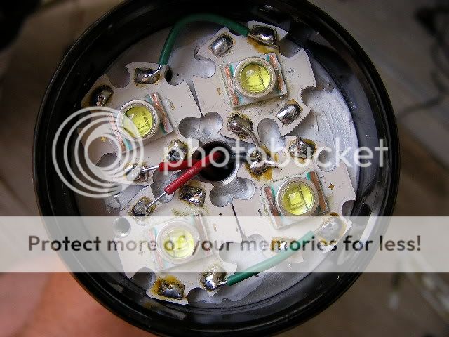
I used thermal grease under the Cree XRE stars in this case, and then wired them up just like so.
The (-) sides of the stars are nearest the wire inlet hole in the heatsink.
Load in some batteries with the tailcap off and try it out with a dc ampmeter and cross your fingers. :duck:
830 milliamps on some old batteries is quite nice and comfy as the leds are only seeing about 415 milliamps each.
With fresh batteries, this light tops out at 1.1 amps which is still not driving them too hard. More than 1.5 amps is hitting them kinda hard.
We're aiming for relliability and runtime for this one this time around.
Now let's make a mess to hold those reflectors still with.
I used black silicone gasket maker for this.
One may use whatever desired to keep the reflectors planted and centered with.
Give that some time to cure.
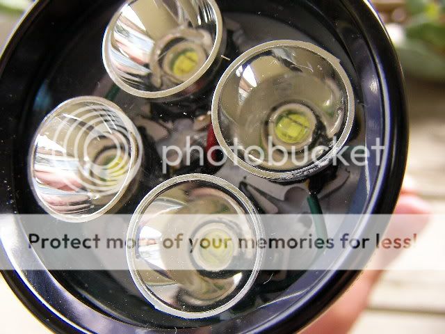
Here is a picture of the completed business end.
A little of that black stuff did ooze in, but is still out of reach of the relatively narrow beam angle of the leds.
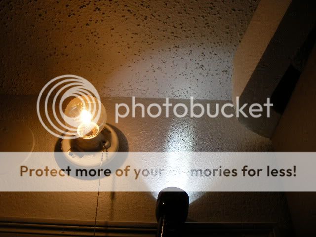
Here it is embarrassing a 60 watt vanity bulb. :laughing:
Now to tackle the C cell
Find and cut some 5/8ths heater hose from the local auto parts store and cut it to 4.5-5 inches in length, then slit it down one side.
3 cr123 batteries, or 2 18500 lithium ion batteries and charger from member AW in the dealers corner at cpf marketplace will also do.
Now cut and reshape the tailspring about a quarter inch shorter so it won't squash the batteries quite so hard.
File, or lightly grind off the sharpest edges off of some SSC P4 led stars.
An adjustable heatsink from member download is used this time.
Mount and glue the stars with thier (-) closest to the center hole with arctic alumina.
Let that cure.
Then file, or shave off any overhanging edges from the stars so that the heatsink can drop right in.
We need to find out what height to adjust the heatsink to.
Put some heatsink grease into it's threads to improve thermal contact between the 2 pieces of the heatsink.
Here is a video of it being adjusted in another, but older pre-2001 2c Maglite.
Even I'm still a bit new to this.
http://smg.photobucket.com/albums/v313/3rd_shift/?action=view¤t=SANY0089.MP4.flv
Loosely assemble everything like this and adjust the heatsink height until everything fits ok.
Be careful not to damage or destroy the fragile gelatin domes from doing this.
Some older obsolete luxeon1 stars can be used instead for this step if preferred.
Once that's done and everything fits good in the Maglite head, we need to stop the heatsink from turning any more.
I used blobs of silicone gasket maker for this and let it cure.
Now apply plenty of heatsink grease at the bottom of the Maglite head, it's threads and the sides inside for best possible thermal contact and conductivity from the heatsink's bottom and top pieces.
Perfect. There is heatsink grease there to catch and transfer heat from the top piece of the 2 piece adjustable heatsink assembly.
Reinstall the wired switch assembly (see the D cell assembly for more on this) with your 5/64ths allen wrench and arctic alumina a 2 watt rated 1.5 ohm resistor just like so.
The two 4-5 inch long red (+) wires are coming from it.
It's other end is soldered to the center tab contact of the switch assembly.
Too much heatsink grease just isn't enough is it? :laughing:
Here is a blurry photo of the C cell's wiring. :huh2:
See the D cell assembly for a clearer picture of the same series parallel wiring, my bad.
Load in some batteries and try it out with a dc ampmeter.
This one pulls about 1.2 amps from 2 lithium ion 18500 batteries.
This is a healthy power draw for this light with these leds at 600 milliamps per led.
This light is close to 600 lumens and can still be left on for quite a while without getting too hot. :twothumbs
This next step is a good idea to keep those metal 17mm reflectors from sliding around and scraping off the soft gel domes from the SSC P4 leds. :green:
Regular 2 part epoxy was used in this case.
Apply it to the tops of the emitter flanges without it getting onto the domes themselves.
Then apply it to the bottoms of the reflectors and set them down on top of the led shoulders and "bullseye" center them as you do.
Let it cure hard 1st with the flashlight standing straight up.
Do not install the bezel yet.
If some excess runs down onto the stars, that is actually good.
We want that to happen in this case for a good adhesive grip to hold the reflectors still and centered when the bezel is put back on later.
Beamshots! :naughty:
Here it is also embarrassing a 60 watt vanity bulb.
On the right is the 6D 4x Cree XRE at 9 volts x 1.1 amps.
Center is a 2c MiniMonsterQuad with 4 WWOT Luxeon5 leds at 7.5 volts x 3.5 amps.
Left is the 2c 4X USWOH SSC P4 led at 7.5 volts X 1.2 amps.
Same lights versus a Thor 15 million candlepower rated cordless gelcell spotlight.
Happy modding! :thumbsup:
Last edited:
 )
)