how do you protect li-ion batteries for a pack?

jspeybro

Enlightened
Joined
Aug 13, 2009
Messages
586
Location
Belgium
Hi,

I'm in the process of preparing to build a cannister for a divelight. I'm wondering what kind of lithium ion batteries you guys use and how you protect these batteries from over(dis)charging.
I was planning to put 2 or 3 LiIons batteries in series and then connect several strings of these in parallel.

I've been searching on this forum and the internet, but am still unsure what I need.
Obviously I need batteries, question is, how should I protect them?
There are the batteries that have their own protection circuit, and there are separate circuits to protect several batteries in series.

From that, I assume it is best not to use protected cells, since if 1 of the cells shuts off while charging or discharging, the entire series string would stop working.
When using unprotected cells, what protection circuit do you use? what specifications should I check?

I'm aware there are protection circuits for the number of batteries in series (switch off at the right voltages). Anything else I should check?
I noticed some people mention things about ballancing. Is this something that should be taken care of in the electronics or is that something the charger does? of is that not so important for such packs in a cannister?

I plan to use a H6CC driver with an SST-50 so I assume that it should be able to handle the current?

Sorry for the many questions...

Johan
 
Johan,

Yes, when you build your own packs of multiple Li-ion batteries you need to source unprotected cells, and then protect the pack with a PCB. As you rightly surmised, an individually protected battery will likely interfere with the packs PCB (Protection Circuit Board).

I used to use Panasonic brand 2600mAh 18650 batteries but now just use the cheapest on DX as the price difference is less than half. Li-ion's don't keep original capacity forever regardless of use, so expect to upgrade down the track and that also justifies going for cheapest. The PCB can always be re-used on the next pack.

I use the PCB's from Batteryjunction.com and the batteries come from DX or KD.
http://www.batteryjunction.com/pcb.html
Batteryspace charges like a wounded bull for international postage so unless it's something I can't source elsewhere I don't use them.

PCBs will protect against all the 'usual suspects'; overcharge, overdischarge, overdraw, and as Pack said, you can now get intelligent one's that will equalise across the cells (only seen these ones on Batteryspace and never used one).

Unbalancing
The more cells you have, and/or the higher the power draw, and especially if you use different branded batteries in the same pack you will eventually have the cells at different voltages. Even if everything starts the same sooner or later the slight differences in internal resitance will unbalance your pack to a noticeable degree. With a PCB attached this will then limit your capacity as the pack will cut-out when the lowest voltage cell reaches the minimum threshold first, and then while charging will show full when the highest voltage cell reaches capacity first.

The solution is to balance your cells, preferably every time you charge. For this you need a balance charger. Balance chargers are reasonably priced and found on DX and EBay. Most use the JST plug for interface so when building your pack you will need to source one of these. Balance chargers usually have an LCD screen so you can monitor the voltage of the individual cells as they charge. When each cell reaches max it stops, or slows the charging while the others keep charging and catch up. Once all the cells are at the same max voltage it will indicate fully charged.

A handy little voltage checker I use in the field is this one;
http://www.dealextreme.com/details.dx/sku.10787
It plugs into the JST plug on your battery pack. Scrolls through the individual cell voltages and then gives the overall voltage. You can use it to check battery balance as well as its overall capacity. At only $3 you can throw one in your battery box, plus if the body of your torch is transparent (or if you machine a window) you can monitor power levels while underwater.
 
Last edited:
Klem:
Just FYI I have tested many of the LiIons from DX and found that the cheapest only have about 1/2 the advertised capacity. They really suck. The 2 for $10 green or blue (ultra or trust fires) are some of their best and have about 200-300 ma less than advertised.

If the run time is OK with the ones you have all is great, however if you are relying on the run time to be true, the more expensive ones are the better ones.

I read about the capacity issue of the DX batteries...
any batteries that you can recommend?
 
Another question best asked in another forum... like this one http://www.candlepowerforums.com/vb/forumdisplay.php?f=9
I wasn't sure posting it there or here, but since many people here use the 18650 LiIon's, in similar packs, I thought I better ask here.
I use PCB's from battery space. The 3S version also balances the battery pack which is quite cool. I saw the same board in a pic of a Salvo (?) battery pack.
http://www.batteryspace.com/pcbbmscmbfordiy.aspx

are you talking about this board: http://www.batteryspace.com/pcmwithequilibriumfunctionandfuelgaugefor111vli-ionbatterypackat10alimit.aspx

as Klem already indicated, batteryspace's shipping doesn't look so interesting, but I'll check anyway.

I see that I need to connect each battery to the circuit board. Do I need 1 board for each series of batteries when connecting multiple in parallel?
Or will the batteries be connected in series and parallel such that the batteries of 2 series strings are actually also connected in parallel (hope that sentence makes sens...)?
 
bro,

I think I know what you mean...No, you only need one protection circuit for the pack, which will be made up of any number of batteries connected in parallel and then in series to make the voltage you want.

You do need to source the correct PCB for the number of cells you want to build.

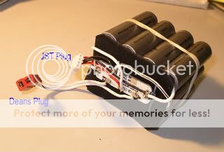
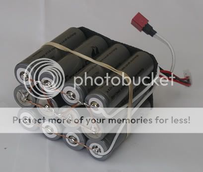
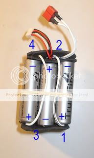
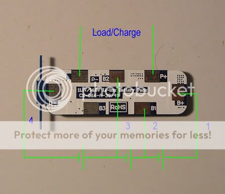
Probably easier to have a look at these pictures. This is a 10Ah 11.1V (3 cell) pack made up of 12*18650 batteries. Each cell is a row of 4 batteries connected in parallel, and then these rows or 'cells' are connected in series with the other rows to make up the 3 cells.

Compare the circuit diagram with the numbered leads in the photo. You will see how the four leads come up to the PCB.

This PCB can be used for either a 3 cell or 4 cell pack. In a 3-cell the contact marked 'B3' is ignored.

The JST plug is for balance charging and has its 4 leads connected to the batteries using the solder pads of the PCB. If you want to balance charge then check the charger as it will have the polarity marked on the plug port. You then plug in the JST to see what plug lead needs to go to what cell join.


batterypack.jpg
battery3bottom.jpg

battery2.jpg
batterycircuit.jpg

PCBexamples.jpg


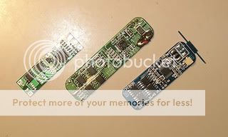
Some examples of 3-cell PCBs above. The one on the left is 3 Amp limited while the two on the right are 5Amp.
 
Last edited:
Thanks, that picture of how the cells are connecten, just what I needed.
I guess I should be able to select a circuit board now and figured I should use unprotected cells (suggestions still welcome ;-) ).

Some examples of 3-cell PCBs above. The one on the left is 3 Amp limited while the two on the right are 5Amp.

So, let's say I want to use the battery pack with a H6CC driver and an SST-50 on 5A. The driver and led will consume about 20W from the pack. For a pack at 11.1V (3x3.7V), this would result in a current draw of about 1.85A. For this, a 3A circuit could be fine, correct? On the other hand, when the battery voltage goes down, the current increases, so when the batteries switch of at 2.75Vx3V, the system will be drawing 2.5A, closer but still within specs of a 3A circuit I would say.

How about charging? Untill now, I only used these simple DX chargers for 2 batteries. Works fine for them, but not for charging a pack.
If I would use a 3S3P setup, how much current would flow in when charging?

Johan
 
Thanks, that picture of how the cells are connecten, just what I needed.
I guess I should be able to select a circuit board now and figured I should use unprotected cells (suggestions still welcome ;-) ).


So, let's say I want to use the battery pack with a H6CC driver and an SST-50 on 5A. The driver and led will consume about 20W from the pack. For a pack at 11.1V (3x3.7V), this would result in a current draw of about 1.85A. For this, a 3A circuit could be fine, correct? On the other hand, when the battery voltage goes down, the current increases, so when the batteries switch of at 2.75Vx3V, the system will be drawing 2.5A, closer but still within specs of a 3A circuit I would say.

How about charging? Untill now, I only used these simple DX chargers for 2 batteries. Works fine for them, but not for charging a pack.
If I would use a 3S3P setup, how much current would flow in when charging?

Johan

Why would you want to feed so a high voltage to such a low Vf LED? You are better off with 7.4V going into the driver...

Here are some of the batteries that I have tested to be quality:
Protected:
http://www.dealextreme.com/details.dx/sku.26247
Unprotected:
http://www.dealextreme.com/details.dx/sku.26248
http://www.dealextreme.com/details.dx/sku.6979

Don't buy anything with quotation marks around the mah that means they are overrated. These cells I have linked have tested pretty consistently at 2400mah-2500mah. I have ought some of their cheapest and you would be lucky to get 1000mah.
 
Last edited:
I have also used these http://www.dealextreme.com/details.dx/sku.6979

And also the protected version.

I have had very few ( if any ) issues with them and they offer good capacity. I have been so happy with them that I have not ever used anything else except for the 4 amp26650's from Battery space which have a safer chemistry.

BE VERY CAREFUL SOLDERING THESE CELLS!
You shouldnt solder to them but instead use a CD welder which are quite easy to make.
In saying that I have soldered these cells my self. The trick is to use a hot iron and to it as fast as possible.
 
Why would you want to feed so a high voltage to such a low Vf LED? You are better off with 7.4V going into the driver...

You are probably thinking about low efficiency "drivers". And in that case, yes, you want to keep the high voltage on the pack from getting too high as you would be wasting a "lot" of energy (most of these low cost drivers from Asia achieve 60-70% efficiency or lower at the higher voltages).

Now note the OP mentioned the H6CC. That is a "very" high efficiency driver, in the 80-90%+, which actually does awesome with the higher pack voltages. George (owner/designer) has some charts on his web site showing efficiency at various loads, and at various input voltage ranges (something you will NEVER get from a driver from Asia as it would only make them look really bad).

George's designs are "the" best LED drivers, tested to perform over a large temp range, by a very experienced EE, and every single one is tested before being shipped out. Bottom line, you get what you paid for.
 
bro,

Yes, as the voltage drops the current draw increases to maintain the power needed. As you probably know rechargeable Li-ion's start out at 4.15V and end up at 3V when the PCB cuts off the power. If no PCB the torch would keep sucking power until the batteries were permanently damaged, which occurs below 2.5V.

Yes, packs are made up from unprotected batteries.

As for charging, you can do this two ways; either through the PCB to the cells, or bypass the PCB and directly into the cells. In the above photos the Deans plug goes through the PCB, while the JST plug for the balance charger goes directly to the cells.

You do not have to go through the PCB for charging as the charger's regulate the operation cutting off when they detect the battery is full. If you choose to balance charge then you can't go through the PCB anyway, plus you will need a second plug for power-out to use the PCB. If you don't want to balance charge then its power in/out via the PCB with one plug only.

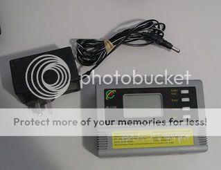
Here are two chargers I can use on this pack.
chargerbalance.jpg
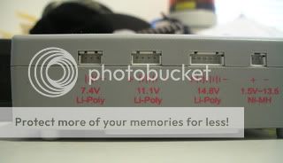
balancechargerports.jpg

Note; the plug ports are different sizes for different size packs, and very helpful in showing which leads in the plug should go where. Don't worry that they might say Li-Po, it works on Li-ion. On that, this one gives a choice of three max voltages; 4.14V, 4.25V and 4.35V per cell. If you want to make your Li-ion's last, use the lowest...4.15V.

charger2A.jpg


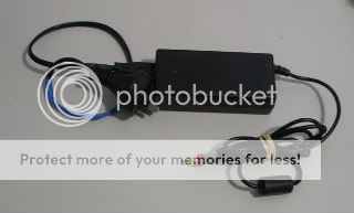
Here's the normal type charger that charges 3-cell Li-ion batteries. Note I've had to cut and solder my choice of plug, which is an 80A rated Deans.

Now, you might want to know why Uncle Klem has two chargers when he only needs one. The normal one is a fast 2Amp charger while the balance is 500mA. With that 10Ahr pack it would take 20hours to charge up using the balance so I juice-up for a few hours using the fast charger, then swap to the balance to equalise the cells and finish the charge. Sometimes I just use the fast charger (you don't have to balance every single time). Takes a lot less time!

Oh, and one more thing... When you build your pack... The individual batteries will have a storage voltage straight out of the packet, but when you put them together and attach the PCB the PCB will probably show no voltage 'empty' across the load/charge terminals. Don't think you've made a mistake like I did, then launch into an email debate with the suppliers demanding your money back. Whack them on the charger and when the PCB low threshold is exceeded the terminals suddenly become 'live'.
 
Last edited:
You are probably thinking about low efficiency "drivers". And in that case, yes, you want to keep the high voltage on the pack from getting too high as you would be wasting a "lot" of energy (most of these low cost drivers from Asia achieve 60-70% efficiency or lower at the higher voltages).

Now note the OP mentioned the H6CC. That is a "very" high efficiency driver, in the 80-90%+, which actually does awesome with the higher pack voltages. George (owner/designer) has some charts on his web site showing efficiency at various loads, and at various input voltage ranges (something you will NEVER get from a driver from Asia as it would only make them look really bad).

George's designs are "the" best LED drivers, tested to perform over a large temp range, by a very experienced EE, and every single one is tested before being shipped out. Bottom line, you get what you paid for.

Good to know. Thanks. I am actually ordering some.
 
Hi,

thanks for al the usefull info.

I'll have a look at those batteries. I'm aware soldering directly on batteries is not a very good idea so I'll see how I get around this. (maybe I can get a friend to bring them from the US... then I could use US websites more cheap :)

I'm indeed going to use the H6CC driver. Unfortunately this driver gets more efficient when using more LEDs. With only one LED, efficiency is somewhere around 85% if I remember correctly, but still not bad.

I haven't decided on how many batteries in series. I just used 3 as an example for the calculation. I suppose 2 in series is probably the better choice for this driver and LED.

about the amps used for charging, if you put more batteries in parrallel, I guess you'll need more amps to get it to charge in an equal time?

anyway, I'm most likely going to use an OMS cannister like 350xfire if I can get one, so 9 or 10 18650's should go in together with the protection circuit. The 9 or 10 will probably decide on how much batteries will be put in series (3 if it is 9 batteries, 2 if it is 10).
 
bro,

If you scratch up the ends of the batteries with rough sandpaper the solder will take quicker. A second or two of soldering doesn't seem to hurt the battery to any noticeable extent.

I put a blob of solder on the end of the battery first, then let it cool. Holding a heat-sink on the spot like the tip of a pair of pliers helps. Then get the wire ready and quickly re-flow and affix the wire. Cool with the pliers again and 'Bobs your Uncle'.

A 2S5P (using 10*18650 batteries) will give you about 12Ahr capacity. With 20W of power consumption at 7.2V average plus a small amount of inefficiency in that quality driver, that's about 3Amps.

The pack should give you 4 hours of light.
 
If you scratch up the ends of the batteries with rough sandpaper the solder will take quicker. A second or two of soldering doesn't seem to hurt the battery to any noticeable extent.
+1

It also helps if you apply a little bit of liquid flux to help the solder "stick" properly/quickly. My favorite/best flux is not that expensive, and comes in a easy to apply pen:
FLUX PEN WATER SOLUBLE 2331-ZX

Just wipe off with some alcohol once you are done.

Will
 
Interesting.

When I post a link to Dealextreme it gets deleted - even though I can't find anything in the Forum rules against doing it !
 
Any Aussies interesting in doing a shared purchase of Batteryspace Protection PCBs to share the absurd cost for international postage ?

I need a 4S board that can handle high output current and Batteryspace seem to be the only supplier in one-offs.
 
Interesting.

When I post a link to Dealextreme it gets deleted - even though I can't find anything in the Forum rules against doing it !

Dude you can only post links to those items that sell for $500 and only if the sellers pay their dues to CPF!
 
Top