Hi folks. First post here.
I recently bought a couple of LED driver modules as well as a couple of 3 Watt LED modules from an EBAY supplier called "lightobject.com".
I got the goodies quickly and am anxious to play with them.
The LEDs are straightforward enough, but no documentation came with this order, and I've searched their site for data and come up empty.
So I'm looking for any advice or tech data that anyone might have for the little 3-Watt (750mA) driver modules that I got. I don't even know the true pinout for them, so that makes things a bit spooky")
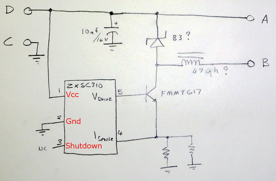
I suppose I could try to trace the circuits out and see if I can look up the active parts by the numbers on them, but I figured someone here may have used these modules and will know the lowdown.
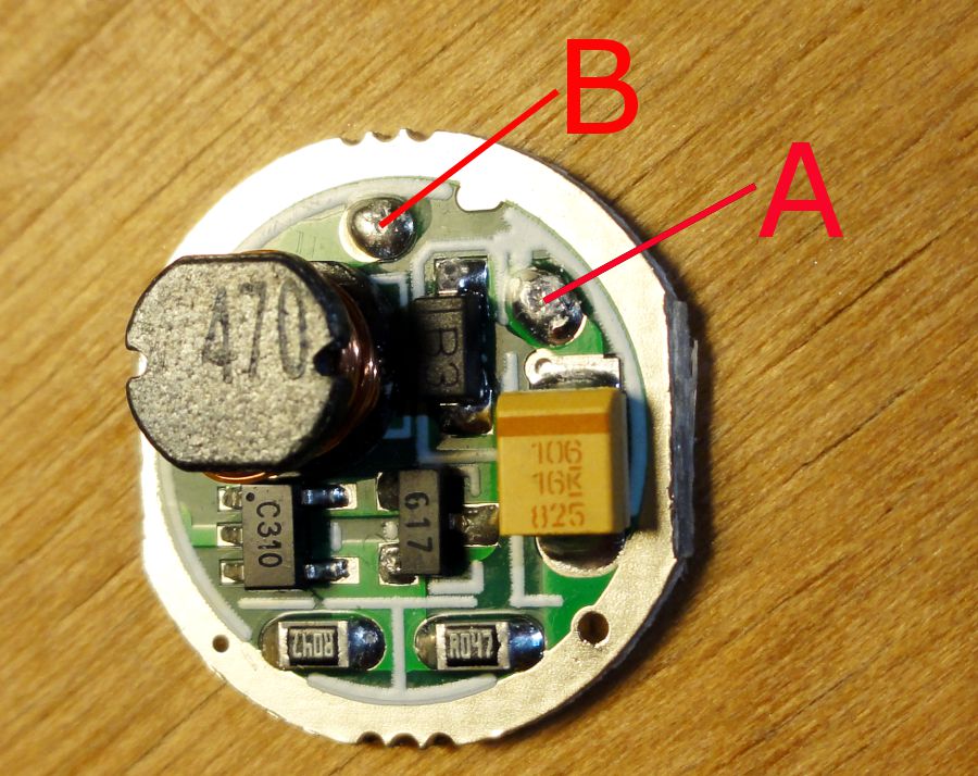
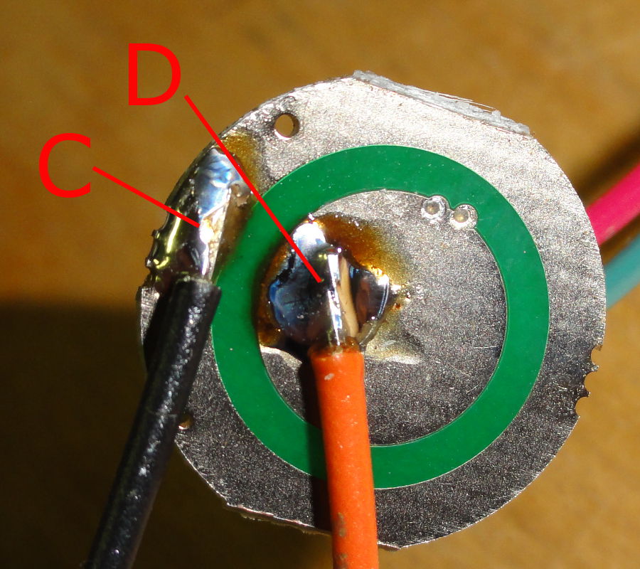
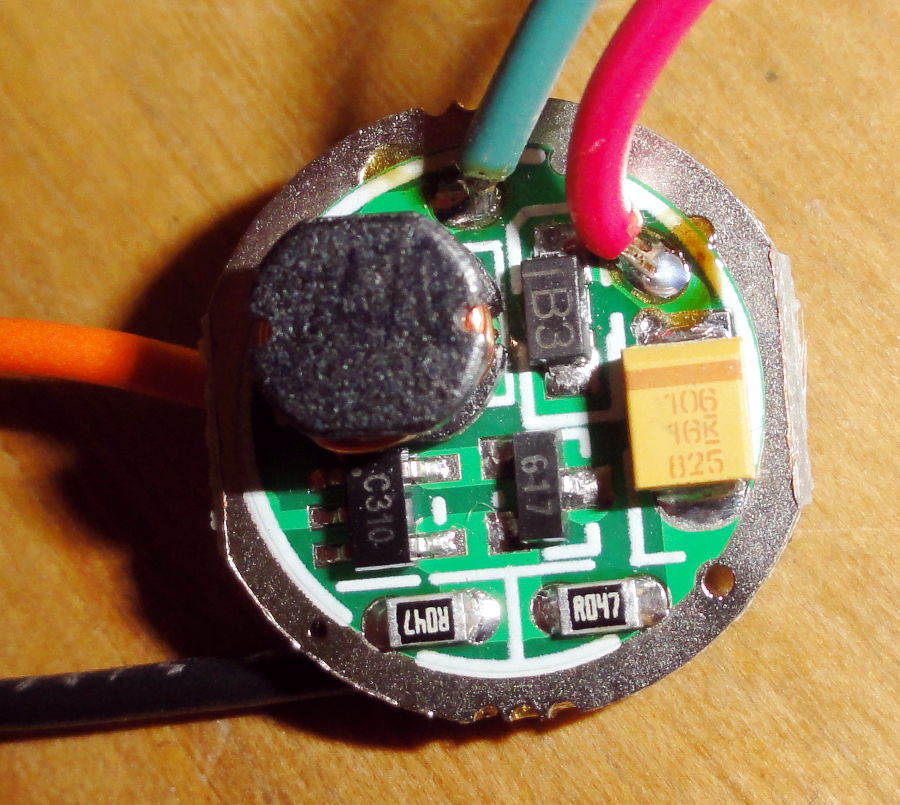
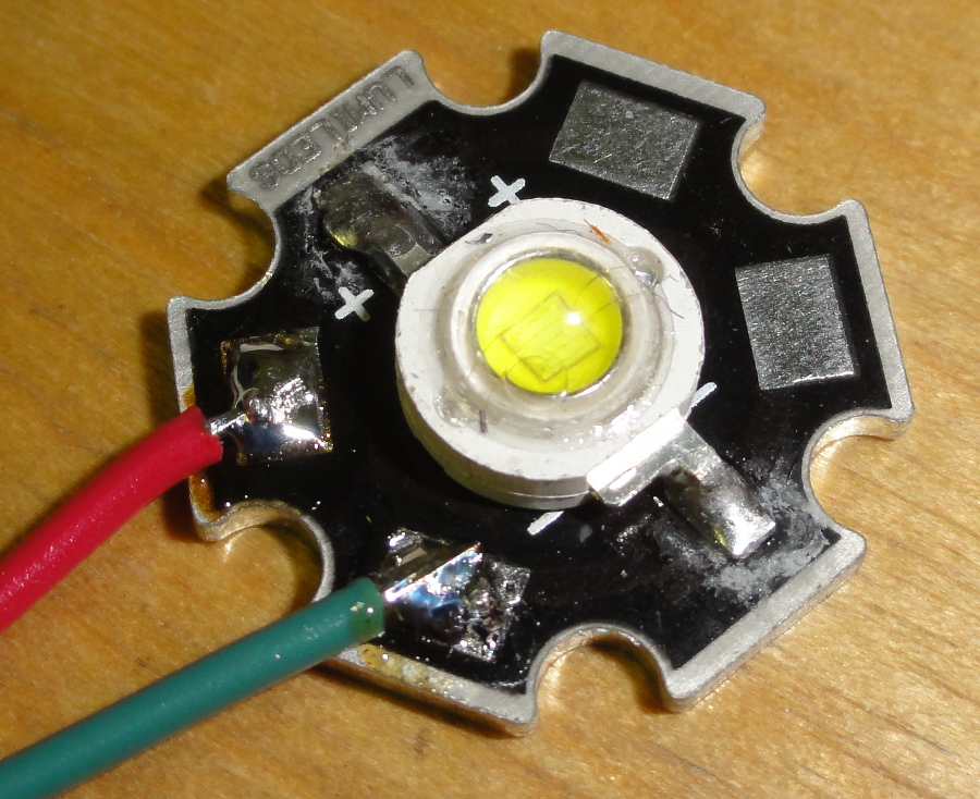
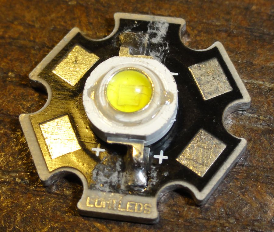
Here are some photos of the modules and one of the LED module just for good measure.
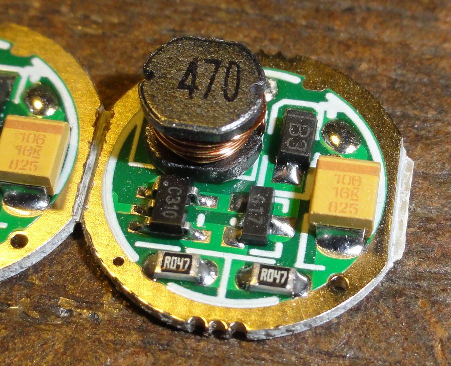
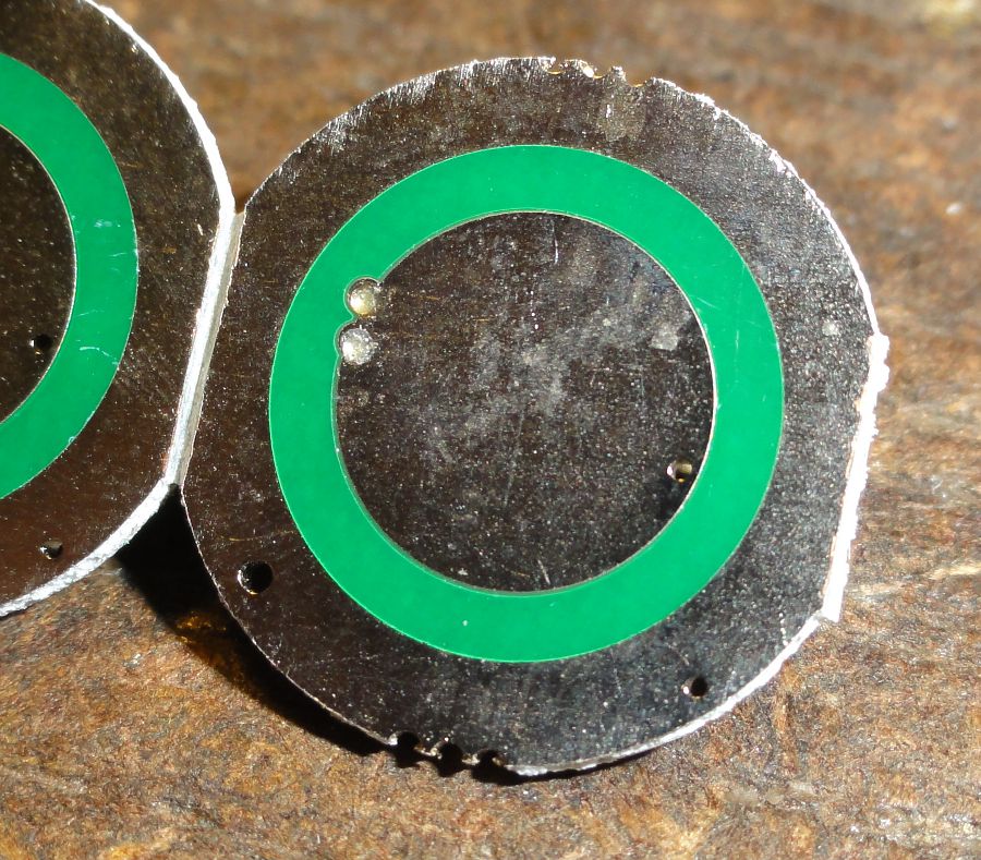
Now. It looks to me like the non-component side of the driver module ought to be the input side with the center "dot" being the positive power input and the ring around the edge being the negative input feed. I figure this would let someone just mount the module in the end of a typical flashlight barrel and the "tip" of a AA battery would make contact with the center "dot" and the outer ring would contact the barrel of the light.
Then, that would leave the two terminals on the other (component) side of the board as the output to feed the LED. On that side, I'd imagine that the outer ring would, again, be the negative side of things (common to the ring on the back, and connected by a couple of feed-throughs - aka plated-through-holes). So the other "terminal" would naturally be the positive feed to the LED.
But, on the website for this company, there is a post to a forum that shows the guy feeding power into the component side of the board, and driving the LED from the back side. Then there's a post below that one with a guy stating that he tried it that way, and it doesn't work.
So I'm thinking that the post showing the power applied to the component side of the board is wrong.
What do you folks say?
I know this is a dumb post, but I'm new to all of this, so there ya go!
Sigmo
I recently bought a couple of LED driver modules as well as a couple of 3 Watt LED modules from an EBAY supplier called "lightobject.com".
I got the goodies quickly and am anxious to play with them.
The LEDs are straightforward enough, but no documentation came with this order, and I've searched their site for data and come up empty.
So I'm looking for any advice or tech data that anyone might have for the little 3-Watt (750mA) driver modules that I got. I don't even know the true pinout for them, so that makes things a bit spooky
I suppose I could try to trace the circuits out and see if I can look up the active parts by the numbers on them, but I figured someone here may have used these modules and will know the lowdown.
Here are some photos of the modules and one of the LED module just for good measure.
Now. It looks to me like the non-component side of the driver module ought to be the input side with the center "dot" being the positive power input and the ring around the edge being the negative input feed. I figure this would let someone just mount the module in the end of a typical flashlight barrel and the "tip" of a AA battery would make contact with the center "dot" and the outer ring would contact the barrel of the light.
Then, that would leave the two terminals on the other (component) side of the board as the output to feed the LED. On that side, I'd imagine that the outer ring would, again, be the negative side of things (common to the ring on the back, and connected by a couple of feed-throughs - aka plated-through-holes). So the other "terminal" would naturally be the positive feed to the LED.
But, on the website for this company, there is a post to a forum that shows the guy feeding power into the component side of the board, and driving the LED from the back side. Then there's a post below that one with a guy stating that he tried it that way, and it doesn't work.
So I'm thinking that the post showing the power applied to the component side of the board is wrong.
What do you folks say?
I know this is a dumb post, but I'm new to all of this, so there ya go!
Sigmo