You are using an out of date browser. It may not display this or other websites correctly.
You should upgrade or use an alternative browser.
You should upgrade or use an alternative browser.
LED Home Made Canister Light
- Thread starter CBR-runner
- Start date
 Help Support Candle Power Flashlight Forum
Alan B
Flashlight Enthusiast
This is clearly a direct drive PWM resistored setup. Are you running 16V battery into 10V of LEDs? What is the Vf on those R2's?
I'm trying to think of a wrong current limit resistor value that would lead to constant-on with this setup, and I don't think there is one.
This is very similar to the hotwire regulator I am building, with the addition of a resistor for the LED current.
I wouldn't call this a buck driver. No inductor.
Last edited:
wquiles
Flashaholic
+1. Something does not add up ...I wouldn't call this a buck driver. No inductor.
Bimmerboy
Flashlight Enthusiast
+1. Something does not add up ...
Well, the price certainly does... lol.
I'm about the furthest thing from being an EE, but that does look like a linear type driver. That to-220 package thing in the middle looks like a LM317, or some similar item. This is probably why you have to specify Vbatt and LED Vf when ordering.
CBR-runner
Newly Enlightened
Yeah I told him 4 r-2's then switched to 3 P-7s. So it was my bad. 
wquiles
Flashaholic
Well, the price certainly does... lol.
I'm about the furthest thing from being an EE, but that does look like a linear type driver. That to-220 package thing in the middle looks like a LM317, or some similar item. This is probably why you have to specify Vbatt and LED Vf when ordering.
The TO-220 can still be a FET (since the product claims to support up to/around 9Amps), being controlled by the micro/PIC/whatever, and this is how the PWM can be adjusted somewhat. Like Alan said, it is hard to know for sure without an schematic, but the fact that you have to let him know the voltages/details before hand do point to some sort of programmable micro and/or resistor divider.
Alan B
Flashlight Enthusiast
At 9 amps the transistor would overheat in linear mode without a heatsink, so I'm guessing this must be pulse width modulated (PWM) and that is an FET switch which will not dissipate much at 9 amps as long as it is in switch mode.
If that is the case, those three larger resistors are probably the LED current limit resistors. With 16V input and 10V across the LEDs the resistors will be dissipating 6/16 of the power, and the efficiency will be a little low but still 10/16 is getting to the LEDs. I'd be a little concerned about those resistors overheating, they are not well cooled.
There's nothing wrong with this approach, but it would be best if the battery voltage was closer to the LED voltage.
CBR-runner
Newly Enlightened
The guy really seems to know his stuff. So I don't question it. It also means I don't have to design and build my own switch and circuit. I was really impressed with the pezio switch. Hopefully it all comes together soon.
I am not an EE so I just figure out what kind of light output i'm going for and buy the stuff that people have made.
Some times I'm successful... some times but I learn either way.
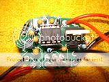
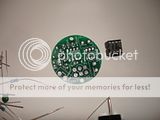
here are some close ups for the EE types... (i believe he does have patent rights)


I am not an EE so I just figure out what kind of light output i'm going for and buy the stuff that people have made.
Some times I'm successful... some times
 but I learn either way.
 here are some close ups for the EE types... (i believe he does have patent rights)


Alan B
Flashlight Enthusiast
I don't know that any of this is patentable, but these days you never know. Instead he seems to be going for "trade secret", hiding the parts, etc. I'm sure we could figure it all out, but I'm not going to do that. This is not rocket science.
I hope it works out for you. At this point my suspicion is that it is already shorted. Hopefully your LEDs aren't injured, changing from 4 to 3 would increase the current a lot, possibly beyond what they can handle. The switch should probably still work, depending on the FET, but it seems shorted at this point.
These parts are very static sensitive, so assembly should take place in a static controlled environment. Even installation may be sensitive and could zap the semiconductors.
The piezo switch sounds neat, is it rated to handle the pressures? Or will the pressure simply trigger it?? If you mentioned this early in the thread, I read it all but that was a long time ago.
CBR-runner
Newly Enlightened
Well the Led's still light up so I assume they are ok. The battery pack I was using was only 12v. I have not purchased the 16v battery pack yet. The fact that the light strobes then went to high defiantly makes me think I blew something up.
I don't know how to test a pezio switch but it changes its resistance when I push on it :ironic:.
Hopefully I did not scare anyone with the patent thing. I'm making sure I cover my :whoopin:.
Alan B I was reading through some of your design stuff. It is very impressive. Hopefully I can find the time to learn more about this stuff latter.
CBR-runner
Newly Enlightened
Well my new IC chip is on the way. should be here in a few weeks. :huh:
In the meantime I think I have sourced a hybrid metallic gasket for the lens. This should make the seal and lens easier and cheaper than making the standard stepped lens. Just need a 3mm sheet of tempered glass and a guy (or girl) to cut it into a circle :thumbsup:
In the meantime I think I have sourced a hybrid metallic gasket for the lens. This should make the seal and lens easier and cheaper than making the standard stepped lens. Just need a 3mm sheet of tempered glass and a guy (or girl) to cut it into a circle :thumbsup:
Bimmerboy
Flashlight Enthusiast
The TO-220 can still be a FET (since the product claims to support up to/around 9Amps)
Right... because, of course, a 317, or "similar item" isn't designed for 9A.
 Just testin' ya', Will!... lol.
 Maybe one of these days I'll qualify as "knows just enough to be dangerous" (or perhaps I already do :devil

Anyways, good luck with the fix, CBR!
CBR-runner
Newly Enlightened
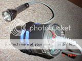
I have started construction of the canister. I figured I'd use 3" PVC for the body. This way I can upgrade the battery if needed.
I'm also adding a battery voltage meter so that can be checked through the canister lid in real time.
Does anyone know where I can get cable glands like these form?


I'm also adding a battery voltage meter so that can be checked through the canister lid in real time.
Does anyone know where I can get cable glands like these form?


Last edited:
CBR-runner
Newly Enlightened
Well thanks to some very helpful posts I was able to find clips and cable glands from McMaster Carr. I ordered 3 of each, clips and glands. Hopefully these things work... tomorrow it is off to the rubber and gasket shop for o-rings, x-rings, and hopefully backing rings.
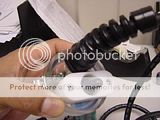
Here are some pics of the glands and clips. These were much cheaper than the diverite replacement parts....


Here are some pics of the glands and clips. These were much cheaper than the diverite replacement parts....


CBR-runner
Newly Enlightened
I have not finished yet I have run into some problems with the electronics and getting a lens that will work...
Thanks for the interest.
Thanks for the interest.


