Forgot to mention that I bought the enhanced reflector which provides a 20% increase in output over the stock reflector due to it's superior coating. I won't install it until I have the entire system up and running reliably and some time on the new lamp.
You are using an out of date browser. It may not display this or other websites correctly.
You should upgrade or use an alternative browser.
You should upgrade or use an alternative browser.
My Holy Grail Has Been Found - Parts of One Anyway - SX-16 NightSun
- Thread starter BVH
- Start date

FRITZHID
Flashlight Enthusiast
Bvh, I sent you a txt regarding your switch issue
For the electronic guru....Are the little "disk" shaped components that tie across all the power input cables where they enter the light, capacitors? And if so what is their purpose. It seems strange to have a component that appears to be "shorting" positive power to negative power. Although I know that that is not happening. I see this happening in all of my power supplies. Look at the orange disks in the 3rd from the bottom pic.
To answer my own question...The maintenance and troubleshooting manual is quite extensive and quite detailed, including troubleshooting sections on all the booster and ignition components. To paraphrase the manual on Caps C11, C12 and C13 (the little orange ceramic disk capacitors that are installed across many of the input connector cables) These ceramic disk caps are CRITICAL to searchlight starting. They act as an RF shunt and complete the RF circuit between the lamp and high-voltage transformer. If any of these has failed, the lamp will not start.
It is very surprising to find that such small parts simply installed across the + and - input cables are essential to starting the lamp.

I don't find a published figure on Lumens but assuming 30 Lumens per Watt, it would be in the neighborhood of 48,000 but could be as much as 40 Lumens per Watt for 64,000 Lumens. Here's some other specs:
Lamp Type: 1600 Watt Short Arc Xenon
Peak Beam Intensity: 30-40 Million candlepower *** increase by 20% (?) due to enhanced reflector
Beam Width: 4-20°(remote control focus)
Typical Range: 3200 ft (1km) *** increase by 20% (?) due to enhanced reflector
Useful Range For Target ID: 1 Mile (1.6km) *** increase by 20% (?) due to enhanced reflector
Peak Illuminance @ 1km: 32 Lux (2.9 ft-cd) *** increase by 20% (?) due to enhanced reflector
Diameter at 10% of Peak Illuminance: 230 ft (70m) @ .6m (1km)
I have no practical use for using it but its fun just acquiring it and getting it working.
Last edited:
I have no practical use for using it but its fun just acquiring it and getting it working.
The final part you need in your quest is a helicopter. :laughing:
Lux, you've got that right! I have a fixed wing license but not a rotor wing ticket - oh well!
Finally decided to take the light chassis out of the can to be sure to get all the glass fragments out and to inspect all the ignitor components, ensuring nothing is burned up. As I expected, everything looks new or super low time.
The back end of the chassis

The Front End. The reflector has 3 1/4" rods attached to it back that go thru the white bushings. Right and Left magnets for manipulating the arc.

The Ignitor PC Board

Side and other misc views of transformers

Echo63
Flashlight Enthusiast
Somewhere between 45 and 65 thousand lumens - it depends on the efficiency of the unit (how many lumens per watt)That looks like a huge light. What is it used for? Lighting up the moon?
Any idea how many lumens?
Its not like you can just measure one in an integrating sphere - the guys who fly the helicopter in the picture below reckon it will melt tarmac at 100 feet (probably not true, but it will be producing a lot of heat still)
they are typically found hanging on the side of helicopters
one of our local police helicopters has a nitesun like this
the other has a trakkalight (i think - its been a while since i went for a flight in it, and spoke to the crew)
Heres the older Police Helicopter with the Nitesun (Polair61)

Last edited:
Little bits of work accomplished as parts are received.
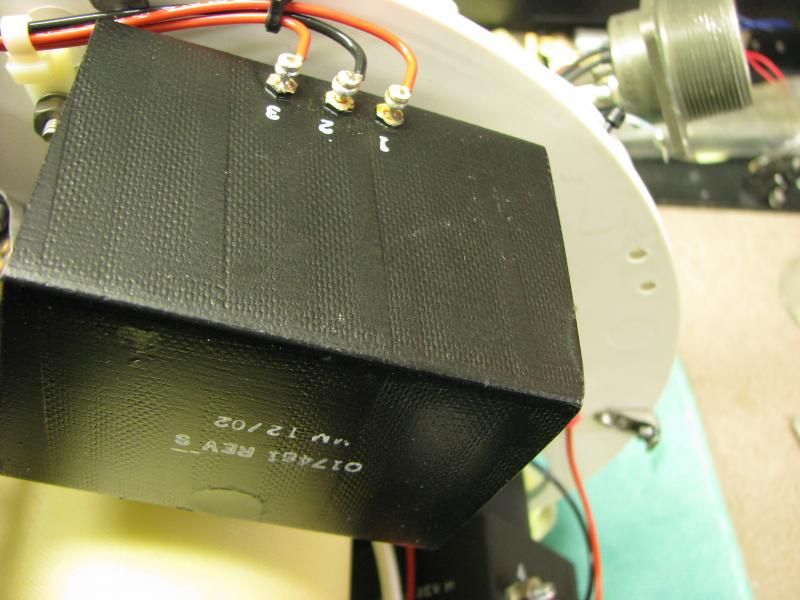
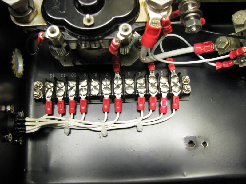
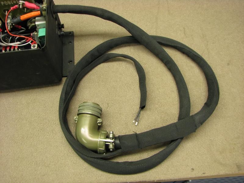
Converted normally hardwired Control box connection to a Quick Connect Amphenol system.
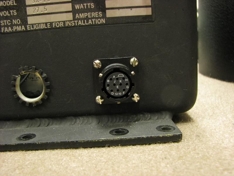
Getting harder as I get older to do soldering like this. 10, tightly clustered #20 AWG pin connections on the fitting at left. Then applied shrink tube.
New, higher capacity CAP - a production change after my production date. Helps hot re-starts

Converted normally hardwired Control box connection to a Quick Connect Amphenol system.

Getting harder as I get older to do soldering like this. 10, tightly clustered #20 AWG pin connections on the fitting at left. Then applied shrink tube.

New, higher capacity CAP - a production change after my production date. Helps hot re-starts

Taschenlampe Dude
Newly Enlightened
- Joined
- Sep 29, 2011
- Messages
- 88
That makes for a very nice, clean installation between the Amphenol jack and the terminal strip. It looks stock!
That was and always is my goal on these military and military-like lights - to do as much as I can to make it look stock. Here, I'm finally getting around to load testing my Lorain Rectifier at an amount equal, + or -, to the NS load. That's 3 ea., Q4559x 28V/22A landing lights. Load on the meter shows 62A and on my clamp meter, 67A. At the recommendation of the NS manual, I bought some clip-on, flip-up #3 welding/braising glasses.
Camera is stopped way down to avoid blindness


Camera is stopped way down to avoid blindness


bshanahan14rulz
Flashlight Enthusiast
I think I see the concrete floor melting!
Great work on that terminal strip, and the amp connector looks like it belongs very well!
Next step: rewind transformer to run on 110 mains? heh heh.
So, how much did it cost you to run 3ph power into your garage? Nevermind, don't answer that, I don't want to know >.<
Always enjoy watching your progress as you restore life into old lumen cannons!
Thats one of the great features of the inexpensive Lorains - the 22-29 Volt, 100 Amp model runs on 240 VAC single phase. Max input is 21 Amps @ 240 VAC.
Timothybil
Flashlight Enthusiast
Just to clarify, what a vibrator is is basically a solenoid reed switch, wired so that energizing the coil removes power from the coil as the NC contact is opened. This re-energizes the coil - rinse, repeat - at a reasonable frequency. Hence the name 'vibrator'. The input voltage is also connected to the NO contact such that while the coil is energized the voltage appears at the output of the vibrator, in the form of a DC square wave. This square wave is sufficient to energize a regular transformer (with a really big iron core to handle the square wave) and produce the required higher voltage at the output of the transformer. This is then smoothed, usually by a large power capacitor. At no time is there any AC voltage present, since the current flow never reverses. The DC square wave produced by the making and breaking of the vibrator contacts is sufficient to cause the varying magnetic flux in the transformer necessary to produce a higher voltage output. In effect, an electro-mechanical reasonably stable oscillator. My understanding is that if the unit was operating while the case was open, the buzz was quite annoying.
Don't mind me, I'm just an old coot with a lot of weird esoterica floating around inside my brain. Have fun play//// experimenting with your new equipment.
Don't mind me, I'm just an old coot with a lot of weird esoterica floating around inside my brain. Have fun play//// experimenting with your new equipment.
mattheww50
Flashlight Enthusiast
NO DC power on the input side, however the output of the transformer will be AC (rather ugly looking in fact) even if fed by a DC square wave in the primary. Output of the transformer is directly proportional the rate of change of current flow through the primary. You get positive voltage when the rate of change is positive (switch in vibrator closes), and negative voltage when the rate of change is negative (switch in Vibrartor opens). So you need a rectifer in addition to the Capacitor bank. There is often a fairly nasty voltage kick on the switch when opens up the lead to the transformer. This often leads to short life on the Vibrator as the contact is slowly vaporized. The bad news is vibrator supplies are very electrically noisy from the make and break contact in the vibrator. And the Buzz tended to be annoying anytime the vehicle was stopped and/or the volume was low.
BTW, if you need more power, you use something called a Dynamotor, which is basically a DC motor and a DC or AC generator (often with multiple windings) on the same shaft. These were commonly used on Aircraft until the 1950's to convert 24VDC to 300-500 volts required for the vacuum tube equipment. I don't think I have seen a Dynamotor in use for 40+ years).
BTW, if you need more power, you use something called a Dynamotor, which is basically a DC motor and a DC or AC generator (often with multiple windings) on the same shaft. These were commonly used on Aircraft until the 1950's to convert 24VDC to 300-500 volts required for the vacuum tube equipment. I don't think I have seen a Dynamotor in use for 40+ years).
Timothybil
Flashlight Enthusiast
I stand corrected. There is a very good description with diagrams of the internals of a vibrator and how it works here http://radioremembered.org/vpwrsup.htm.
The Dynamotor was also known as a motor-gen set, with a motor running at available voltage, current, and frequency and driving a generator whose output was the desired voltage & frequency. Until the advent of switching power supplies almost any mainframe computer room had one for converting the 60-cycle AC available to usually 400-cycle, mainly because one could then use smaller transformers and rectifiers in the power supplies. Larger versions are also still in use in areas, mainly farms, where three phase power is needed but is not available from the local utility. A large single phase AC motor will drive a three phase generator to drive the load.
The Dynamotor was also known as a motor-gen set, with a motor running at available voltage, current, and frequency and driving a generator whose output was the desired voltage & frequency. Until the advent of switching power supplies almost any mainframe computer room had one for converting the 60-cycle AC available to usually 400-cycle, mainly because one could then use smaller transformers and rectifiers in the power supplies. Larger versions are also still in use in areas, mainly farms, where three phase power is needed but is not available from the local utility. A large single phase AC motor will drive a three phase generator to drive the load.
In the manual it indicates that the vibrator output is 48 VAC square wave @ 60 htz
")
An update. I've installed the new "used" lamp, bonded the new front window to the bezel and finished making a new cable from the junction box to the lights' connector. This is usually a 5-conductor but I added two extra 16 awg wires that exits in a small loom right before the connector. The purpose of this will be to provide the additional wire I need to upgrade the lights' current single direction focusing system to bi-directional. Member FritzHID has graciously made me a small multi-relay board that will switch polarity to the focus motor on demand from the new OEM thumb focus switch I purchased from Spectrolab and will install in the control box. I couldn't simply use a reverse polarity rocker switch because I need to supply a ground signal to the hot side of the motor when it is not running to prevent motor coasting and drifting when not in use. However, this task will be done once I fire up the light for the first time to verify that everything actually works. I'm also not going to install the new higher performing reflector until the light has proven itself.
Fritz also did some #6 awg cable soldering for me on the quick-connect Amphenol power connectors to the junction box I am installing. The #4 awg pins are not removable from the rubber insulator and only about 1/8" of the pins' solder cup was expose above the rubber. I don't have the equipment necessary to do the job within these constraints. The connectors and relay board arrive this afternoon in the post. Once the quick connector is installed and wired in, I'm ready to do final circuit tracing and confirmation and then apply power. It's kinda scary doing this for the first time. I have no idea if the electronics in the junction box and the ignition components in the light actually work.
For focusing adjustments, they provide two methods in the manual – a short-distance (10 meters) and an optimal distance (100 meters). Since I don't live on acreage, the 10 meter will have to do. In this case, they recommend shining the beam on a completely non-combustible, flat surface capable of withstanding 500F temperatures and painting it black. I purchased my flip-down #3 welders shades so I don't incur eye damage. I'm actually still trying to figure out how I can even do the 10-meter test. I need a 2 meter flat metal surface, I need 33' of distance from the light and 240 VAC power supply and I really DON'T need to attract any attention.


Last edited:
Similar threads
- Replies
- 0
- Views
- 830
- Replies
- 107
- Views
- 23K