SKU 26106 5xCree 15W driver schematics + 12V mod

HansV

Newly Enlightened
Joined
Mar 9, 2010
Messages
70
Location
Norway
I'm not sure it this belongs here, but I will give it a try.

I have manage to reverse engineer the SKU 26106 5xCree 15W driver board from DX and made a schematic. I have also identified the switching regulator on the board, that's AS2001 from Anisem:)
Having done this, I verified that the regulator also will work fine for 12V battery voltage. The only modification needed is to change the value of the series resistor R4(marked with a circle) from 150ohm to 1Kohm. This is the large 1206 resistor marked "151". this is a zener shunt regulator, and will draw about 50mA with a 150ohm resistor and generate too much heat. It could work still, but I would not recomend it.
The switching reguator is spesified up to 15V, and the other components is not a problem. The only thing is that the input voltage needs på be lower that the output voltage for the LED's.
The switching transistor can handle 30V, and the peak voltages are actually lower with 12V supply voltage. The power dissipation should also be lower because the current is reduced.

If a driver without the 5 modes is needed, just move the LED- wire to the sense resistors (R1/R12). Then the mode switch is disabled.

Hope anyone else finds this useful. I was wondering if I could use this board on a 12V battery, and now I know:)

Edit
Here is link to the schematics, that I converted to jpg:
http://img511.imageshack.us/img511/3064/driverboard15w.jpg


A short discription on how it works:
- U2 is the controller/ASIC that is used to make the modes.
- R6/C4/C2 is timing for mode switiching
- R4/D3 is a 5V shunt voltage regulator
- U1 is the boost switching controller (AS2001)
- T1/T2 is drivers to speed up the gate switching and reduce switching losses
- L1/D1/Q1/C1 is the boost circuit
- D5 will limit max. output voltage when the LED is disconnected or Q2 switched of, to avoid overvoltage on Q1
- Q2 is the current switch to controll the PWM/blinking for the modes
- R1/R12 is current sens resistors, with a constant 0.5V drop
- C5/R11 controls the switching frequency
- R9 controls the output drive current on pin5
- C6 is reference voltage filter cap
- C7/R10 is soft start timing

Hope this will help someone. This is a nice and flexible circuit that easily can be modded:)
 
Last edited:
hi,

i also done some mod´s on this driver. i often got problems with the charge-cap from the setp-up output section, so i always replaced it with a better cap from an old mainboard or so...

evgl-1.jpg


markus

p.s. why can´t you post the shematics here?
 
The voltage rating on the output cap seems to be OK(20V), but I think the switching current is too high. That is probably the reason that it breaks. Good quality 25V capacitors or cheramic multilayer caps should do the trick.
I have now uploaded the schematichs on ImageShack, it was too late to figure out how yesterday when I found out that I could not post the pdf file directly here on the board.
 
Last edited:
Post more mods or report other problems with this driver board here, and I will update the schematichs and the top post!
It's a good driver design, but the componets are a bit cheap(OK for 4$:). Therefor it is usefull to know what tends to break so it can be upgraded in advance to avoid problems.

Possible mods is for example to make a constant voltage output regulator in stead of constant current. That is easy with this board, just replace D5 with a resistor and connect output GND to board GND:)

Other possibilities is to replace the mode controller(U2) with another controller circuit to get other modes. Just connect 5V, GND and the control signal to R3/Q2 gate. It works with 3-15V control voltage on the gate and does not pull any current other than through the pull-down (R2).

For higher output current it is possible to upgrade L1, Q1, D1, C1 and C3. If the switching frequency is increased, the value of L1 can be lower to reduce inductor loss.

The switching circuit can be turend completly off by disconnecting R9, with for example a switch or a transistor.

I quess there are other possibilities as well, to fit specific needs. The input voltage is always limited to 15V because of the switching regulator, but the output can be higher if Q1 is changed to a higher voltage MOSFET. Then it scould be possible to drive 6, 7 or 8 LED's. Driving 3-4 LED's should work fine without any modifications.
 
I can't be sure, because the driver board manufacturer has removed the text on the IC, but it's not FP6201. The pins doesn't match.
FP5138B has correct pinning and functionality, but doesn't come in SSOP8 package.
I still think AS2001 from Anisem is the regulator used here, but there could apperently be others that is compatible/interchangeble. Then it realy does not matter witch one they have use, as long as we can understand how it works and modify it.

http://www.yasemi.com.cn/pdf/AS2001_Preliminary_080303.pdf
 
Simple mods for better performance

As mash.m stated, the charge capacitor (C1) on this board is underrated and prone to break. I have now tested alternative capacitors for performance.
I found that when I replaced C1 with a 10uF ceramic capacitor(1210 25V X5R), the input current dropped 50mA (at 8V input). The reduced power was mostly burned up in the tantalium. Use two capacitors in parallel to get the same value as before if you want, it will reduce ripple but is't nessesary.
I also changed R4 to a 1kohm 1206 resistor, enabeling the board to work fine with 5-15V input voltage.
One more modification I have done was to replace the rectifier diode(D1) with two BYS10-45 diodes to reduce the diode loss. They have lower forward voltage.
Increasing the frequency by changing R11 to 6.8k(150kHz) or 5kohm(200kHz) also reduces the loss in the switcher. I simply soldered another 10Kohm resistor on top of R11.

Newark parts list suggestion:
10uF 1210: 10R6036
BYS10-45: 96K7236
1Kohm 1206: 53K1779
10kohm 0603: 52K8062

I managed to drop the input power with about 1W with these modifications, so it is easy to increase the efficiancy of this board.

I recomend eneryone using this board and have the skills to change the capacitor for lower loss and better reliability.
If the board will see more that 8V, I also recomend to change R4.
The other mods is not nessesary, but will increase efficiancy. Higher frequency will also give better regulation.
 
HansV,

Thank you for taking the time to post all of this. What value do you recommend for R4 if driving this from 8xAA NiMH? (~10V-6.4V over the discharge)

Also, do you have a recipie for increasing output current (to ~1400mA) to drive 4 XP-G emitters in series? Or is that asking way too much of this board?
 
1Kohm for R4 works down to 5V, so you can use that. 470ohm would also work fine.
For 1.4A you will need 0.5V/1.4A=0.36ohm. Maybe 3x1ohm resistors in parallel works? R12 (the 4.7ohm on top) can also be changed to 0.68ohm.
I will test this when I can and see if the board can handle this. You should definitly change the capacitor C1 when increasing the current.

Edit:
3x1ohm in parallel for sense resistor gives about 1.42A drive current.
I have tested this with load similar to four LED's. It seems that the rectifier diode(s) gets to hot with this current. Measured almost 90 degrees C on the diodes with 6V input voltage. Put this inside a hot flashlight, and it may not last long. The transistor seems to operate fine around 60-70 deg and the inductor is only 35-40 deg.
You can try connecting two driver boards togeather and strap the control signal from one board to the other, that should work fine. Do you want the modes, if not it is just to connect them in parallel.
Another solution is to replace the rectifier diode with a schottky power diode that can take the current. A TO-220 package can be heatsinked to the flashlight.

Or you can just modify the board and see how long it lasts. It could work just fine. If you mount the board so it's not enclosed in the heat sink/LED mounting base it will ceep cooler. You can put it the other way around or mount it sideways.
Just get a spare driver board or two, so you can repace it if it burns up. The components that is stressed when you increese the current is Q1, C1 and D1. All these can be replaced to deliver a lot more current. Just monitor the temperatures when you test it. It will get warmest with the lowest input voltage.
 
Last edited:
When increesing the current on this board, the regulation becomes unstable and gets a audible low frequency noise.
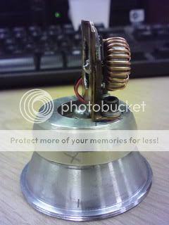
This is caused by radiation from the big inductor picked up by the board and interfreing with the current regulator. It can be fixed by moving the inductor away from the board like this:
moddriverboard.jpg

This is a good modification it there is room for it. Now you also have the possibility to add a heat sink on top of the transistor and diode to cool it down. Small heat sinks for motherboards that is glued on should be fine. The inductor can also be placed vertically and the wires can be swapped or extended if needed.
This board now has a 10uF cheramic 1210 capacitor for smoothing and 3x1ohm parallel for current sense. Works fine, but gets hot at lower voltages.
Unstabillity in the regulator is not a big problem if you don't mind the noise, so this driver should work fine even without this mod.
 
I used this board with a DX 3×cree dropin in a maglite. I thought it best to try and heat sink the board. I remembered seeing photos from one of you guys using copper tube in a maglite which worked well. So I made something similar. The driver is soldered to the copper plate via the outer solder ring (neg). I cut a hole in the centre of the plate to clear the Pos connection.

DSC00074.jpg


The board is std with no modifications.

I measured the current draw on each setting to calculate the Run times. The times are based on using 2000mAh Sanyo eneloop batteries.

High: 1.35A current draw = 1hr 29mins
Medium: 0.84A Current draw = 2hrs 22mins
Low: 0.43A Current draw = 4hrs 39mins

I run it on high one evening with fully charged batteries and got 1 hour 30 mins before it went into a constant flashing mode, which I believe is low battery signal. Amazingly the theory works!
The head and body of the maglite was hot to touch, but not too hot. I put a freash set of batteries in and it worked fine. A great little driver!

Question: What would be the lowest input voltage used on this driver? Could it run 3 LEDs from 3.6V (3AA or 3C) or 4.2V(4AA) ?
 
Hi Essexman,

You can use it for 3*Cree setup with 3*Ni-Mh. If you made resistance fix on Mag.

Here is my setup's runtime using 3*D size Sanyo 4400mAh Ni-Cad in 3*D Mag. Cree MC-E wired 2S2P and driver set for 1450mA.

Mag.Grafik.jpg


Offcourse 4*Ni-Mh will work better.
 
Last edited:
Hi Eprom, thanks for the details. I really like this driver, it has so many uses!

Wow that's some current draw on your D cells!!
 
moddriverboard.jpg

This board now has a 10uF cheramic 1210 capacitor for smoothing and 3x1ohm parallel for current sense.

Hi,

since all the components on this picture are visible, would anyone mind to mark the R4 that should be increased to 1kohm for extended voltage range, the 3x1ohm current sens resistors and the location where I should solder the led- wire to disable the modes?

This would be my first driver mod, so I'd like to be sure I'm doing it right.

Also, I'd be interested in a better quality schematic since the text is hardly readable in the JPG in the OP.

edit: seems the 'single-mode-mod' was already mentioned here so that is solved.
I also used a multimeter to measure some resistances. Is the 150Ohm the one that I should upgrade to 1kOhm?
 
Last edited:
does the inductor needs to be close to the board, or can I extend the leads a bit and put it on the other side of a heatsink (as if there would be a 10mm heatsink between the board and the inductor)?

The inductor is slightly too large for the space I have.
or maybe I could get an inductor that is a little smaller?
 
Make the wires as long as you like - you're just adding a little bit of inductance to a lot of inductance !

But -
- use at least the same diameter wire, so you don't get resistive losses.
- don't run the wires close to the electronics on the board - this can cause instability
- if the run will be long, twist the two wires around each other.
 
I need a Boost Converter to charge a LiIon battery with 16.8 volts from 12 volts - this module will be ideal - with the Mode switch bypassed.
 
Top