Standlight and Martin's Circuit 12 help please!

piesoup

Newly Enlightened
Joined
Oct 31, 2008
Messages
114
Location
East Anglia
I was really hoping for a good result. But I remember you saying there WILL be issues!

The pin outs on the footprints in easyEDA are not correct and I trusted them unfortunately. I have had to change 5 of the transistors. I have bought a few as spares luckily, but I was hoping to make another board up with the extra bits!
I'll be able to use little wires to get the layout right.

Thanks for the tips about testing it gradually, I will do that as soon as I have the parts soldered in the correct position.

I have certainly learnt my lesson!
 

Steve K

Flashlight Enthusiast
Joined
Jun 10, 2002
Messages
2,786
Location
Peoria, IL
I suppose every hobby or area of knowledge has these sorts of learning curves. The phrase "measure twice, cut once" applies to woodworking and carpentry and probably lot of other stuff. For electronics, I always check my board layout against the schematic with a highlighter, verifying that each pin is connected to the right thing. Keeping the datasheet handy for the parts is helpful too, just to confirm that I really do know which pin is the gate, etc.

It probably helps to know that bad things will happen and to plan for it. Always buy spare parts, put time in the schedule for rework, and don't get discouraged. Even when you've done everything right, there will be a time when you hook things up and turn it on, and either nothing happens or there is a small "pop" and a little bit of smoke comes out. Just curse softly and start investigating what happened. It's good preparation for times at work when something bad happens and everyone expects you to fix it (even when you didn't cause it). :)
 

piesoup

Newly Enlightened
Joined
Oct 31, 2008
Messages
114
Location
East Anglia
It works!!!!!! Well I always knew your circuit would, just if my soldering and pcb would.

I nearly had had another catastrophe though. The PS at work doesn't have current limiting. So as I was winding up the voltage, the current was rising too much. Q1 was starting to get hot and smoked a little. When I turned it all off I remembered the athe dynamo is current limiting. I think Q1 is still OK as it worked on my ride home. Phew!

But...
is the wheel on your recumbent a 26inch wheel? The light comes on at 6mph with some serious flicker. That settles down at 20mph and the second pair of LEDs turn on at 26mph. Too fast for me.

Should I be looking to reduce the value of R1 and or R2? Easier than playing with the caps I suppose.

And for the flicker, would the value of R15 & R16 need looking at? I remember you saying you added those and the two caps to he reduce the flicker.

Also, if Q1 is indeed knackered, would this increase the flicker?

On my mtb the wheel / tyre combo will be even bigger and the speeds a lot slower. I may need to look at another circuit for that. But my race is in 12 days so I will try and get this one running. Anyway. I spun the wheel by hand in the dark garage and its BRIGHT!
 

Steve K

Flashlight Enthusiast
Joined
Jun 10, 2002
Messages
2,786
Location
Peoria, IL
On my bikes, I don't notice the flicker above .. 8 or 10mph? The second pair of LEDs should be turning on at something close to 13 or 14 mph, so my first guess is that the full-wave rectifier is only a half-wave rectifier. I'd recommend making sure all of the mosfets are working.
 

piesoup

Newly Enlightened
Joined
Oct 31, 2008
Messages
114
Location
East Anglia
Smashing, thanks!
I worked out the difference speeds meant you wheel would have been the size of a kiddies bike, so I was convinced there was a duff component. I have a spare mosfet, thanks for your help yet again.
 

Steve K

Flashlight Enthusiast
Joined
Jun 10, 2002
Messages
2,786
Location
Peoria, IL
You're just lucky that the failures have been conveniently obvious! :)

It's stuff like this that makes an oscilloscope a very handy tool. When I was having trouble figuring out why the light would flicker between 2 and 4 LEDs around the switch-over speed, the 'scope helped me see that I had some odd spikes on what I expected to be a simple rectified sinewave. It took the use of a circuit simulator and some educated guessing to actually figure out what the problem was.

Of course, duplicating someone else's design does limit the sort of problems you'll run into. Good luck!
 

piesoup

Newly Enlightened
Joined
Oct 31, 2008
Messages
114
Location
East Anglia
Untitled by Andrew Fraser, on Flickr

Well its all together, complete with jumper wires! Please excuse the horrendous soldering, I will blame my cheap soldering iron, but we all know that a bad workman...

I've replaced all the MOSFETs with new ones and I'll plug it in to the dynamo this evening. Fingers crossed the flicker has gone!

The standlight starts off very bright, then dims after a few seconds. It stays dim forever but that could be due to the huge battery I used.
I'm using an XML led as opposed to the XRE? ones you used. Cant see that being an issue as the newer leds are more efficient. I'm not too concerned about it at this stage, but something to look at after my race.

I'll be sure to video the light in action on Saturday night to show you!

Thanks again for all your time Steve
 

Steve K

Flashlight Enthusiast
Joined
Jun 10, 2002
Messages
2,786
Location
Peoria, IL
Well its all together, complete with jumper wires! Please excuse the horrendous soldering, I will blame my cheap soldering iron, but we all know that a bad workman...

I've replaced all the MOSFETs with new ones and I'll plug it in to the dynamo this evening. Fingers crossed the flicker has gone!

Soldering is an acquired skill. Some of it is understanding the how and where to apply heat, understanding the need for flux, etc., but practice is an important component too. The most important thing is that the solder joints be reliable.

Good luck with the testing!

The standlight starts off very bright, then dims after a few seconds. It stays dim forever but that could be due to the huge battery I used.
I'm using an XML led as opposed to the XRE? ones you used. Cant see that being an issue as the newer leds are more efficient. I'm not too concerned about it at this stage, but something to look at after my race.

I'll be sure to video the light in action on Saturday night to show you!

Thanks again for all your time Steve

I'm not sure I can explain the standlight behavior. My memory has faded, but I recall that you were using my basic circuit. Can you post the schematic again? My versions of that circuit have a very steady output.

a side topic... how big of a priority is waterproofness (if that's a word...)? For home projects, I tend to rely on silicone caulk, a.k.a. RTV, for this purpose. Products like G.E. 280 are commonly available and low cost, but have low enough acidity to not damage the copper (or at least present a limited risk of damage). There are electronics grade RTVs, but tend to be pricey.

Looking forward to the video! :)
 

piesoup

Newly Enlightened
Joined
Oct 31, 2008
Messages
114
Location
East Anglia
Well I'm back!

The race went well, I finished in the top third of the solo riders so chuffed with that.
However I couldn't use the light! As the average speed was so low due to the very sticky mud, it just flashed. A lot. And when I got to 10 mph, I needed a lot of light, but it was only just warming up.
On the road I cant see this being a problem though. There is still too much flicker compared to the K-Lite my friend was using. Although when we riding fast on the road the night before the race, our light was a lot brighter :grin2:!!

I have bought some XPG's to try. I also want to try using three instead of four as there are more lenses available. Would this be a problem?? I'd have two running at slow speed and bring the third one in when I get faster.

I will also play around with the stand light as it shines bright for a few seconds and them dims for a few minutes. Maybe its the battery? maybe a dodgy component on my board.

About the waterproofness (it has to be a real word, is on the internet now!) the box I used was sealed up with RTV. The joys of having had a job in aircraft maintenance!


I will report back after the weekend as the wife and child are away, so I have the weekend in the shed!!
SON one-two w-standlight v01i by Steve Kurt, on Flickr
 

Steve K

Flashlight Enthusiast
Joined
Jun 10, 2002
Messages
2,786
Location
Peoria, IL
Well I'm back!

The race went well, I finished in the top third of the solo riders so chuffed with that.

congrats!

However I couldn't use the light! As the average speed was so low due to the very sticky mud, it just flashed. A lot. And when I got to 10 mph, I needed a lot of light, but it was only just warming up.
On the road I cant see this being a problem though. There is still too much flicker compared to the K-Lite my friend was using. Although when we riding fast on the road the night before the race, our light was a lot brighter :grin2:!!

I have bought some XPG's to try. I also want to try using three instead of four as there are more lenses available. Would this be a problem?? I'd have two running at slow speed and bring the third one in when I get faster.

I think I mentioned it somewhere in the past, but I recommend wiring up some switches to short the extra LEDs manually, and experiment to find out how many LEDs you need, whether 3 LEDs is noticeably brighter than 2 (I'm guessing not), and at what speeds the extra LEDs should be turned on or off. If you are going to be slogging through the muck, perhaps you only want one LED powered at low speeds, and maybe the low speed threshold is closer to 8mph?

I will also play around with the stand light as it shines bright for a few seconds and them dims for a few minutes. Maybe its the battery? maybe a dodgy component on my board.

I think you need to make some voltage measurements on the circuit while it is operating (preferably on the lab bench than on the road, but there are ways to do it on the road too). My guess would be that the battery only has a little charge.... perhaps it is old or has been abused? Or something is wrong with the charging circuit, and it's not charging at a high enough voltage?
I don't know if I've mentioned it, but I always use a nicad AA, as nicad's are more tolerant of trickle charging than NiMH cells.


About the waterproofness (it has to be a real word, is on the internet now!) the box I used was sealed up with RTV. The joys of having had a job in aircraft maintenance!

There is certainly a peace of mind that comes with having a headlight that can tolerate being rained on for hours or getting covered in gunk. I can't imagine why some commercial lights, such as some B&M that I have heard of, aren't sealed well enough to survive heavy rain. Of course, breaking into the sealant material so you can modify the design is a bit of a nuisance. :)
 

piesoup

Newly Enlightened
Joined
Oct 31, 2008
Messages
114
Location
East Anglia
Thanks, it was a hard slog! The mud turned to plasticine once the rain stopped.

I'll only use the light for road riding, with the off road trails being so technical, nothing beats 3000Lm from my homemade XML light. But for the road, this light and a dynamo will be perfect.

I got it set up with 4 XP-Gs, but as the dies are mounted so close together, I cannot get to the individual dies, so the standlight is not hooked up, but the 2 to 4 led switching is. (Quick one on that, I have a new NiCad battery after reading your advice on battery choice elsewhere. Once the flicker is gone, I'll look into why it isn't working) I did have the multimeter tied to the bike roaring to get my 5v system working, the neighbours must think I'm mad!

The flicker is noticeable at up to about 25mph. I am tempted to redo the entire board as there are too many jumpers and its a bit messy.

I'm thinking about a smoothing cap after the MOSFETS??? like on a bridge rectifier. Would this work? Or is that the job of C1 and / or C5? I'm probably way off the mark anyhow!

Here is a pic of the led I am now using. If I can get rid of the flicker and decided if I want 3 or 4 leds, I will use a proper set up with proper reflectors.

A side question... As I don't have a scope, is the voltage after the MOSFETS DC with a big ripple?

I hear ya when it comes to comercial lights not being fully waterproof. Here in the UK, its a must! I'm 3d printing my own enclosures so I can be sure they stay dry. And once I know the board is working properly, I will coat in a clear lacquer just to be sure.


Showing the prototype mess for the 5v stuff
Oversize Pic

Moderator Note
Please follow Rule 3

Alaric
 
Last edited by a moderator:

piesoup

Newly Enlightened
Joined
Oct 31, 2008
Messages
114
Location
East Anglia
Quick update Steve, it works great!
seems to be much less flicker with the XPGs as opposed to the XMLs.
The second pair come in at 15mph and they flicker until 16mph. There is still a slight flicker but it's not a problem.
It's as if the increased load drops the voltage slightly and that causes it? Maybe the XMLs are loading it up too much?
Now to sort out a better optic as the one I cobbled together has a big dark patch right in the middle.
 
Last edited:

Steve K

Flashlight Enthusiast
Joined
Jun 10, 2002
Messages
2,786
Location
Peoria, IL
so things are pretty much working properly? That would be a relief! :)

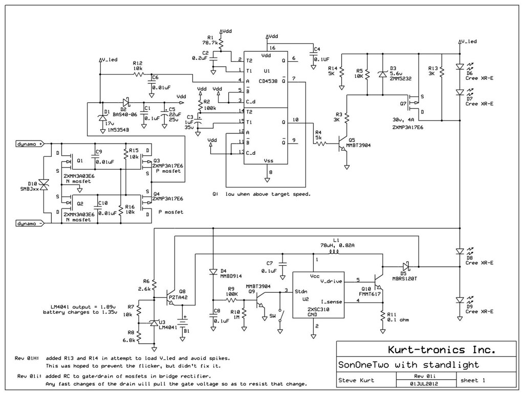
The interaction between the LEDs and the mosfets in the bridge rectifier were a surprise to me, and I was fairly happy to come up with a fix for my light. I didn't bother to consider what might happen with much larger LEDs.

However.... it wouldn't surprise me to learn that the larger LEDs might disrupt the careful balance I achieved with the caps I added at the mosfet gates. The original problem was related to the part of the dynamo's AC output, where the voltage was decreasing. At certain speeds, the rate of decrease of the voltage caused (IIRC) the mosfets to shut off. While the mosfets were shutting off, the current through the LEDs decreased, which removed the load from the dynamo, which caused the dynamo voltage to increase, which caused the mosfets to turn back on, which caused the LEDs to start conducting, which caused the dynamo output voltage to drop, causing the mosfets to turn off, etc....

Adding the caps to the mosfet gates slowed down the turn-off, which reduced the amount of feedback between the LEDs, dynamo, and mosfets. If you have the patience, you might try increasing the value of the caps. Perhaps increase from 0.01uF to 0.022uF? Or just solder another 0.01uf on top of the ones already on the board.

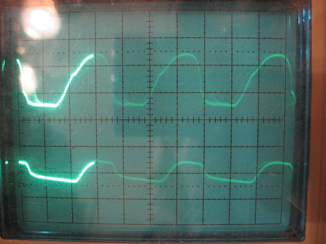
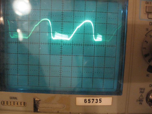
to answer an earlier question... the rectified dynamo voltage that is connected to the LEDs has quite a bit of ripple.. it goes all the way back to zero volts as the dynamo's AC voltage crosses 0 volts.
Here's a scope shot of the rectified voltage:

5368769998_fba0be28ea_z_d.jpg


I'd have to dig through my notes to see what the conditions are.

Without the caps at the mosfet gates, the quick switching of the mosfets on and off caused some nasty spikes on the rectified voltage, which was messing up the circuit that measured the dynamo frequency and producing the flicker that I saw....

5368762956_669c8f6720_z_d.jpg


A scope is a very handy thing to have!! It's hard to justify the purchase if you are just building one project, though.

Going back to your earlier post again.. the mosfets in the bridge rectifier aren't blocking reverse current flow, so you can't add a filter cap. You could add a series diode, preferably a schottky, and then add a filter cap. That might be an interesting exercise.

Regarding your quad LED optics... it can't produce a nice tight beam, can it? I find that I prefer a very tight beam, such as the Ledil Rocket smooth spot, which produces a beam that is +/- 4 degrees FWHM (full width half maximum). My guess is that your reflector produces a much wider beam, and the dark spot might just be the image of the center of your LED group.
 

piesoup

Newly Enlightened
Joined
Oct 31, 2008
Messages
114
Location
East Anglia
Yip! Working as expected! I will play around with the caps like you say. I have some left over I can try. Thanks for the tip.

Thats is great hearing about the way the mosfets and LEDs interact with the rising and falling speeds. I'm a mechanical guy, and the same can be said for hydraulics. That's why we use accumulators. You use capacitors. They do the same thing, amazing!

I thought that that was what the voltage wave form would look like. By using the MOSFETSs over diodes, are you reducing the voltage drop caused by having the diodes? Makes sense when the dynamo can only put out a small amount of power.
Thanks for the pictures, they made it ever tinunderstand.

Ive set up my bike in its stand so the wheel runs on the lathe chuck. Easier then riding around in the dark with a multimeter on the bars. I want to connect up the XMLs again and compare. And the 4 vs three LEDs too. I'll use a camera on auto settings to gauge the brighter setup. Im sure the exif data will show some differences.

That reflector was from a single XML (magicshine) light. It was a very sharp spot which I like too. Now it's horrendous! But it got the light working. Not keen on the overly floody beams either. And the Regina reflectors are a favourite of mine too. I may use them or a Lidl Cute SS triple. I didn't notice much more light when the second pair came on, so I will probably just use a triple.

I have made made a new PCB layout to correct all the mistakes from the first. I've added in extra solder pads for the two caps between the mosfets and a place for a temporary pot to tune the speed when the extra LEDs come in. At the mo it's about 16 mph which is about my cruising speed when loaded with gear, I may move it up or down to reduce the flashing when it switches.

Im tempted to leave out the stand light. I have a small front light that is perfect as a stand light. I'll cobble together a small arduino to turn it on or off whether I'm moving or not. And it can be charged by USB in the day.
But then a piece of me doesn't want to give up on your design, I want to know I've done it!!
 

Steve K

Flashlight Enthusiast
Joined
Jun 10, 2002
Messages
2,786
Location
Peoria, IL
I hope the caps fix the flicker issue. The worst case scenario is that you use schottky diodes, which might be just as good, assuming you don't spend much time at low speeds.

Using a lathe might be helpful for checking out various configurations. I'm not sure that it will be the same as riding the bike, but it doesn't hurt to try it.

I'm still quite fond of built-in standlights, if only because you don't have to worry about whether it is charged or not. But... it's a lower priority than getting the light itself working properly.

and there's the good news.. the days are getting shorter, so you have more opportunities to do tests. :) Have fun!
 

piesoup

Newly Enlightened
Joined
Oct 31, 2008
Messages
114
Location
East Anglia
Well, I have changed the LEDs to XPGs, what a difference! The flicker is hardly noticeable ( I have not added more caps ) and the stand light works perfectly now. Its bright. Brighter than the Klite my friend has.

I now have three LEDs, due to optic availability. From the circuit I have removed the first LED (D6), so two light up at slow speed and the third one comes on when I go faster. But it doesn't turn on the third one.
All the LEDs work as I connected just the V_LED and GND. The circuit is essentially the same. Or does it NEED the load of two LEDs to work correctly?

I will take it apart again and check all the connections, it'll be something I've done!

But even on the two leds, it was sufficient at 25mph on a dark road.

You're right, getting darker earlier now is great. I no longer have to wait until 2230 to go out. But I do now need a jacket which is a shame!
 

Steve K

Flashlight Enthusiast
Joined
Jun 10, 2002
Messages
2,786
Location
Peoria, IL
Well, I have changed the LEDs to XPGs, what a difference! The flicker is hardly noticeable ( I have not added more caps ) and the stand light works perfectly now. Its bright. Brighter than the Klite my friend has.

hmmm.... I'm not sure I understand why the LED change would matter. Electrically, there's not much difference. Any chance that you are using the same optics with both LEDs? It's possible that the smaller XP-G produces a tighter beam, which would look brighter.


I now have three LEDs, due to optic availability. From the circuit I have removed the first LED (D6), so two light up at slow speed and the third one comes on when I go faster. But it doesn't turn on the third one.
All the LEDs work as I connected just the V_LED and GND. The circuit is essentially the same. Or does it NEED the load of two LEDs to work correctly?

I haven't considered it before, but when using the mosfet bridge rectifier, it might be necessary to use two LEDs. This causes the voltage across the LEDs to be 6V, which is what will be applied to the mosfet's gate. With a single LED, only 3V is available at the gate.
Is 3V enough to turn on the mosfet?? Well, let's take a look at the datasheet....
On page 5 of the datasheet is a graph titled "Output Characteristics". This graph shows the Vds vs. Id (drain current) at different Vgs (gate to source voltages). For a Vgs of 3V, we can see that at Vds of 3V, the mosfet is capable of a drain current of around 2.5A. That is much more that will be coming out of a hub dynamo, so I don't think that this should be the problem.

Perhaps the dual one-shot doesn't like low voltages?
Well, looking at the old Motorola datasheet, it can operate at voltages as low as 3V, and the output voltage is normally only 0.05V below the supply voltage. It doesn't seem likely that this is the problem.

I will take it apart again and check all the connections, it'll be something I've done!

But even on the two leds, it was sufficient at 25mph on a dark road.

You're right, getting darker earlier now is great. I no longer have to wait until 2230 to go out. But I do now need a jacket which is a shame!

Check the wiring carefully, measure voltages, etc. I usually write the voltages on the schematic, and this helps me see what voltages look wrong.
Don't feel bad... there can easily be subtle problems that can take time to figure out. Troubleshooting skills are usually developed the same way as muscles.. with a lot of effort, sweating, and a bit of cursing now and then. :)
 

piesoup

Newly Enlightened
Joined
Oct 31, 2008
Messages
114
Location
East Anglia
hmmm.... I'm not sure I understand why the LED change would matter. Electrically, there's not much difference. Any chance that you are using the same optics with both LEDs? It's possible that the smaller XP-G produces a tighter beam, which would look brighter.

Could very well be the case. The XMLs had that reflector a few posts above, the XPGs have a frosted optic. The beam is certainly a lot better, so either way, XPGs for the win! And they work with the stand light. I put an XML on the output for the standlight, it was bright for a few seconds then dimmed. I find it strange as they have a lower Vf and are a lot more efficient.


I haven't considered it before, but when using the mosfet bridge rectifier, it might be necessary to use two LEDs. This causes the voltage across the LEDs to be 6V, which is what will be applied to the mosfet's gate. With a single LED, only 3V is available at the gate.
Is 3V enough to turn on the mosfet?? Well, let's take a look at the datasheet....
On page 5 of the datasheet is a graph titled "Output Characteristics". This graph shows the Vds vs. Id (drain current) at different Vgs (gate to source voltages). For a Vgs of 3V, we can see that at Vds of 3V, the mosfet is capable of a drain current of around 2.5A. That is much more that will be coming out of a hub dynamo, so I don't think that this should be the problem.

Perhaps the dual one-shot doesn't like low voltages?
Well, looking at the old Motorola datasheet, it can operate at voltages as low as 3V, and the output voltage is normally only 0.05V below the supply voltage. It doesn't seem likely that this is the problem.

I will put another XPG in the circuit and see how it goes. If it doesnt work, I will try it with the XMLs as it did work before. Then I know its some dodgy soldering or wiring. 16mph is 1350rpm on the lathe, so it's pretty easy to check.
Thanks for the explanation on reading those graphs, every day is a school day!


Check the wiring carefully, measure voltages, etc. I usually write the voltages on the schematic, and this helps me see what voltages look wrong.
Don't feel bad... there can easily be subtle problems that can take time to figure out. Troubleshooting skills are usually developed the same way as muscles.. with a lot of effort, sweating, and a bit of cursing now and then. :)
I'll do that. I am learning so much on this project, thanks to you!
 

Steve K

Flashlight Enthusiast
Joined
Jun 10, 2002
Messages
2,786
Location
Peoria, IL
hmmm... the change from a reflector to an optic could be the primary reason that the XP-G performs better. Do you know how the beam angles compare, especially with the LED being used?

As for the standlight and the circuit for switching at speed, I'm grasping for ideas. The LEDs, as noted, are electrically very similar. There's nothing weird going on... such as one of them not using an isolated thermal star, and some unintentional connection being made through the star? Or the thermal path on one of them being compromised and allowing the LED to overheat?

Measuring the voltages on the circuit and recording them on the schematic is probably your best shot at figuring this out.

good luck! Better get this wrapped up before the days really get short!
 
Top