piesoup
Newly Enlightened
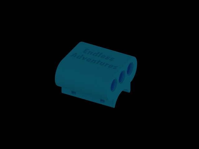
Once i have it working properly, I will try it with the XMLs again. But I think it could be the difference between a whole light head from AliExpress costing £7 (The XML light) verses the Carlco optic on genuine Cree leds from a reputable supplier. One XPG cost more than the entire light from Aliexpress!
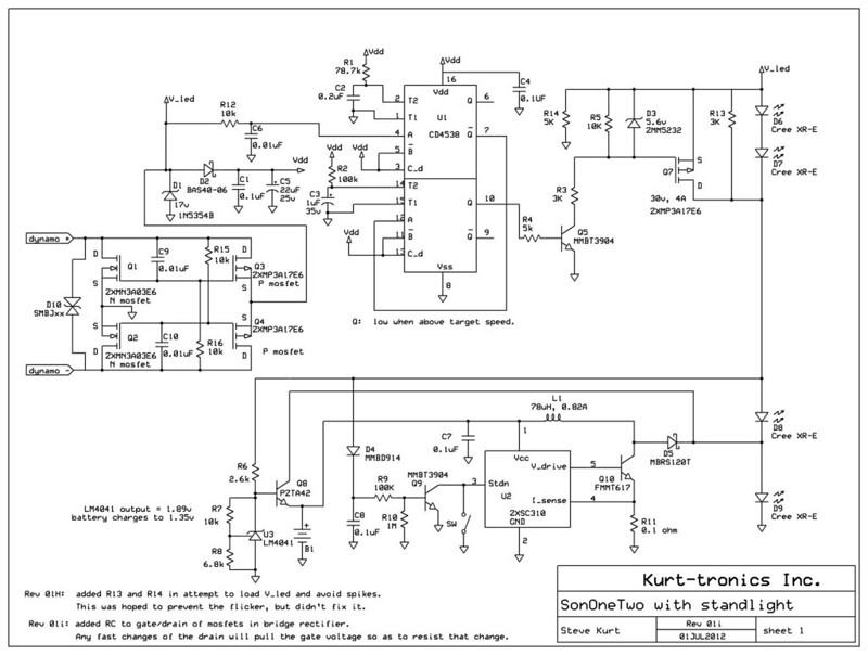
I did manage to measure some voltages, at the higher speed where the second set of LEDs should be ON.
Pin 10 to GND on the mulitvibrator should be low at high speed. Correct?
Under the threshold ( @ 12mph), it is 4.8V. Over the threshold ( @ 24mph), its 5.2V
Vdd seems pretty stable at 5.6v. Which should be as only two LEDs are being powered.
I haven't measured any other voltages as I suppose I need to find out why Pin 10 is still high when above the speed where it should be LOW.
Thing is, i KNOW it used to work. I have checked the continuity, the LEDs are hooked up directly to the board, all seems ok. Should I be measuring Pin 10 to GND with it disconnected from Q5? would that make any difference?
On your older schematics, when you were using Q_not instead of Q, you had a little 'what's happening' on the drawing. I cant quite get my head around how Q5 makes Q7 conduct between Source and Drain. Is that what is happening when the LEDs are shorted out?
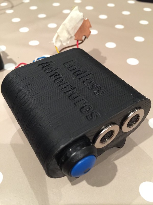
The days are getting shorter quickly. I ride to work in the dark and even with only two of the LEDs lit, its great!
I did manage to measure some voltages, at the higher speed where the second set of LEDs should be ON.
Pin 10 to GND on the mulitvibrator should be low at high speed. Correct?
Under the threshold ( @ 12mph), it is 4.8V. Over the threshold ( @ 24mph), its 5.2V
Vdd seems pretty stable at 5.6v. Which should be as only two LEDs are being powered.
I haven't measured any other voltages as I suppose I need to find out why Pin 10 is still high when above the speed where it should be LOW.
Thing is, i KNOW it used to work. I have checked the continuity, the LEDs are hooked up directly to the board, all seems ok. Should I be measuring Pin 10 to GND with it disconnected from Q5? would that make any difference?
On your older schematics, when you were using Q_not instead of Q, you had a little 'what's happening' on the drawing. I cant quite get my head around how Q5 makes Q7 conduct between Source and Drain. Is that what is happening when the LEDs are shorted out?
The days are getting shorter quickly. I ride to work in the dark and even with only two of the LEDs lit, its great!
")