Standlight vs Voltage Doubler

mbanzi

Newly Enlightened
Joined
Nov 2, 2015
Messages
37
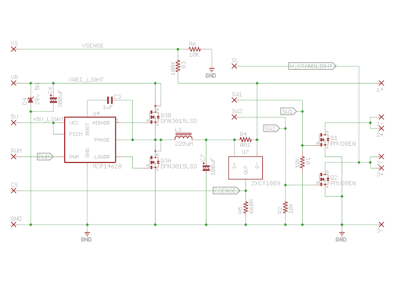
Finally made some more progress tonight with the switching buck regulator. I decided to use minisystem's design and then work from there. I used the same low-ish 32kHz PWM frequency he used & the same component values, with the addition of 2 mosfets to switch out one or two of the series LEDs at lower voltages. Happy to report the regulator worked well, as did switching out the LEDs at lower voltages. At this point I had the ATtiny creating a 32kHz 75% duty cycle PWM waveform. Next I'll add the current & voltage sensing and the MPPT tracking algorithm. I did notice that the current sense voltage was over 5V, so I'll have to take a look at that.

In the picture below the shrink wrap covered PCB is the mosfet rectifier (Steve K's design), ATtiny is the PCB on the left side of the breadboard with the regulator attached to the light.

IMG_3828.JPG


IMG_3827.JPG


Rectifier.png
 

Steve K

Flashlight Enthusiast
Joined
Jun 10, 2002
Messages
2,786
Location
Peoria, IL
cool! :)

it took me a little while to realize that the thing that looks like a buck converter is actually the mosfet gate driver. That makes more sense, at least in terms of implementing a max power tracker.

I'll be interested in seeing the experimental results.

I will say that I've been mulling over the issue of the size of the filter cap that follows the bridge rectifier. It relates to the "need" for the dynamo to feed into a high impedance load. We use a buck converter to change the load from a low resistance LED to a higher (and adjustable) resistance created at the buck's input. My concern is that putting a large-ish cap after the bridge rectifier will just be adding a low impedance load, and that might prevent the dynamo from putting out more than a few watts.

My thought are that the best size of the filter cap would be one that creates an acceptably small ripple voltage at the buck's input. This would let the cap look like a fairly high impedance to the dynamo.

My intent is to run some simulations to prove or disprove this theory... but I've been distracted with other things like filing my federal and state tax forms. :p
I also need to review my LT Spice info and see how to get the simulation to converge quicker/better.
 

mbanzi

Newly Enlightened
Joined
Nov 2, 2015
Messages
37
I will say that I've been mulling over the issue of the size of the filter cap that follows the bridge rectifier. It relates to the "need" for the dynamo to feed into a high impedance load. We use a buck converter to change the load from a low resistance LED to a higher (and adjustable) resistance created at the buck's input. My concern is that putting a large-ish cap after the bridge rectifier will just be adding a low impedance load, and that might prevent the dynamo from putting out more than a few watts.

My thought are that the best size of the filter cap would be one that creates an acceptably small ripple voltage at the buck's input. This would let the cap look like a fairly high impedance to the dynamo.

Thanks Steve that will be great! With the next versions I plan to increase the PWM frequency to the 200-250kHz range, whatever provides enough resolution "steps" in the micro. Then I can also get rid of the massive inductor I have on there.

One problem with using the modules as I have been doing, is that I sometimes miss the big picture. I just realized that the 300uF cap (C6 in the schematic) is connected to the rectifier without a schottky to block reverse current. I also found the issue with the current sensor chip, I had an incorrect footprint in the Eagle CAD library I was using!

This brings up a question: is there still enough of an advantage to using a mosfet rectifier over a low Vf diode bridge rectifier?

Mosfet rectifier advantages:
  • Very low voltage drop (mV)

Mosfet rectifier disadvantages:
  • Input voltage cannot exceed the gate-to-source voltage (Vgs) rating of the mosfets (typically 20v), so has to be clamped <20V (can put a resistor in series with each gate and use a zener clamp between the gate and source of each mosfet to limit the Vgs http://www.thetaeng.com/FETBridge.htm)
  • Requires a schottky diode on output to prevent reverse current flow when used in front of a capacitor input power supply.
  • More complex implementation.

Diode rectifier advantages:
  • Allows full input voltage >20V to be used (may be useful for MPPT)
  • Simple implementation.

Diode rectifier disadvantages:
  • Voltage drop over 2 diodes (this is the biggest single disadvantage in a dynamo application).
 

Steve K

Flashlight Enthusiast
Joined
Jun 10, 2002
Messages
2,786
Location
Peoria, IL
regarding the "big picture"... yep, gotta keep track of the underlying theory and need to figure out ways to test the theory before you spend too much time and money on what might be a dead end. :)

my plan for my simulation is to get a buck converter to work ... I think I mentioned some convergence issues..
The next step is to get the dynamo model to work at the same time as the buck. It might simply not be possible/practical to have a simulation of a 40Hz dynamo running at the same time as a 100kHz buck converter.
If that works out, then try to get data at various dynamo speeds and buck converter duty cycles. This should show if my guesses about appropriate buck duty cycles are correct.

I suspect that this sort of progression would be appropriate for the actual hardware too.

Once things have been mapped out over the range of dynamo speeds and buck duty cycles, then the whole idea of actual peak power point tracking can be explored. That ought to be interesting! It seems like it will require an actual dynamo that is driven by an external motor that can have its speed adjusted. That's beyond my capabilities at this time. Might require some modifications to my wheel truing stand??

Regarding rectifiers: In the short term, I'd go with schottky diodes. Mosfets caused me some issues in my design that switched between 2 and 4 LEDs, mostly because there was oscillation set up between the LEDs and mosfets turning off as the AC waveform decreased in amplitude. Save that little headscratcher for a time when the peak power tracking algorithm has been figured out.
Besides.. the advantage of the mosfet rectifier is when the bike is going very slow. I had a short uphill stretch on my bike commute where I was going about 4mph up a 14% grade. Every little bit of voltage mattered to me! For most people, this won't be a consideration. I would recommend worrying more about the losses in the buck converter and the required precision for tracking the peak power point.

For reference... if it matters.... the tracker that I designed for a 3kW satellite photovoltaic array could track within a handful of watts, IIRC (and I probably don't). The buck converters that were designed by a supplier were about 99% efficient, but did this by minimizing switching losses through the use of a very low switching frequency, and minimizing resistive losses by using rather large inductors. The converters ended up being fairly huge, but I guess the tradeoff is that a smaller PV array was needed.
 

Bandgap

Enlightened
Joined
Aug 14, 2002
Messages
284
Location
London
Hi mbanzi and SteveK

Thanks for trying out the dead-time block mbanzi.

On the subject f waveforms, I agree with what SteveK says.

Just to add: one way to think of the driving waveforms for p and n-channel mosfets combined in that configuration is that for proper operation the waveforms are in-phase (except for the dead-band) - so the two waveforms need to look the same, except for the subtle timing at the edges.

Indeed, inside cmos logic, it is exactly the same signal connected to both mosfets and, instead of dead-time adjustment, the gate characteristics of the two mosfets are very carefully tuned to prevent much shot-through current flowing - and even then, there is some.

You can decide to use inverting or non-inverting drivers depending on what polarity of waveform you have decided to create from the MPU.
As MPUs now allow you to chose to invert either PWM output signal, you just change the software depending on what drivers you can buy.

I also agree with SteveK on mosfet choice.

To add to what he said, do think about gate voltage capability.

Those drivers will alternately connect the gates to the +ve rail and then the -ve (or 0V) rail.
So this means the gates must survive what ever maximum voltage you choose to have on the +ve rail.
As well as that, they have to be fully working at the minimum voltage you intend to operate at. For this, I suggest 4.5V, which is the minimum voltage your driver chips will work at. So, you need to chose mosfets that are turned on well (say <50milliohms (<20m even better)) with 4.5V on their gates, and then can tolerate your maximum chosen +ve rail voltage.

As such, I suggest you manipulate the PWM waveforms to keep the maximum +ve voltage to maybe 16V as it is hard to find mosfets that work well with 4.5V on the gate, but can also survive much more than 20V on their gates.

This gives you a typical hardware engineering issue - with the dynamo running, you will have a circuit that will ruin the gates of the mosfets if you mis-handle the waveform you are feeding them.

A large 18V Zener diode from the +ve to the -ve (0V) rail will keep the gates safe if you make a momentary error, and eat potentially damaging voltage spikes - but will melt if it has to eat the dynamo output full-time.

[Edit] - I realise you have discussed some of this stuff.

The other Steve
 
Last edited:

Bandgap

Enlightened
Joined
Aug 14, 2002
Messages
284
Location
London
Input voltage cannot exceed the gate-to-source voltage (Vgs) rating of the mosfets (typically 20v), so has to be clamped <20V (can put a resistor in series with each gate and use a zener clamp between the gate and source of each mosfet to limit the Vgs http://www.thetaeng.com/FETBridge.htm)
[*]Requires a schottky diode on output to prevent reverse current flow when used in front of a capacitor input power supply.

This is not a problem mbanzi.
Because of the low frequency involved, the resistor and zener combination is easy to design.
Also, use a modification of figure 3 of your reference, only using two mosfets. Keep the two n-channel fets and replace the two p-channel fets with Schottky diodes.
Then the bridge rectifier only has the drop of a single Schottky, and is reverse-blocking.

As any active bridge is going to have the same gate voltage issues as any following buck stage, there is good reason to keep very good control of the total output voltage of the bridge, and this will automatically keep good control of the ac input to the bridge - potentially removing the need for the resistors and Zeners. In this case, I would put a pair of back-to-back 'safety' Zeners on the ac input of the bridge.

The other Steve
 

Bandgap

Enlightened
Joined
Aug 14, 2002
Messages
284
Location
London

Be aware - I think the MCP14628 cannot be used at 100% duty cycle - the upper mosfet will turn off after a pause and leave the load open circuit (as soon as you stop the switching waveform, the top mosfet gets starved of gate drive). An open circuit load will mean the input will climb until the 28V Zener catches it.
By the way, those DMN3015LSD mosfets are only rated at +/-20V on the gates, so they might get fried as I don't think the MCP14628 has any output regulation (I might be wrong!).

More than, say, 16V is not really need on the supply rail as the dynamo is already producing 6W (nominal) when it gets to 12V (nominal)

The TC4431 gate driver in the post a few above that is better in this respect as it will happily work at 100% (and 0%), although it does not drive well below 7V (there is an optional under-voltage lock-out to keep the outputs disconnected below this. My guess is that this is intended for systems with a 12V input rail.
Oddly, the TC1411 driving the other gate in that same circuit is all-cmos and operates well from 4.5V to 16V (abs max 20V). I would be inclined to go for this one for both gates, or the dual one I mentioned in a previous post. Just keep good control of the PWM waveform (I can write a post on this if you need, I claim!!).

The other Steve
 
Last edited:

Bandgap

Enlightened
Joined
Aug 14, 2002
Messages
284
Location
London

Try FIGURE 4: Desktop CPU power supply in the same application note, BUT WITH A P-MOSFET IN THE TOP POSITION (meaning the top waveform would need inverting).
Vdd can be up be anywhere between 4.5V and 18V if the mosfet gates can take it.
And it does not need a separate 5V supply.

The other Steve (who has been quite productive today, as least in this thread....)
 
Last edited:

Steve K

Flashlight Enthusiast
Joined
Jun 10, 2002
Messages
2,786
Location
Peoria, IL
jumping into this quickly... what about the voltage rating of the gate driver?

the datasheet says the boot voltage is limited to 36V. For normal operation around the peak power points, this might be acceptable. My SON data & model says that at 90Hz, the peak power point occurs at 28V.. although that is probably 28V rms, so the peak will be over the 36V limit.

There is the general issue that the SON has been observed to produce 100V at high speeds (50mph), so I think there is a cause for concern here.

It may be adequate to just clamp the SON output to a safe level, but there will need to consider the amount of power dissipated in the clamp circuitry.

I've used 100V mosfets in earlier dynamo circuits where there could be a very light load on the dynamo. In later designs, I've always had the voltage limited to the Vf of 2 to 4 LEDs, so there were no high voltage concerns.
 

mbanzi

Newly Enlightened
Joined
Nov 2, 2015
Messages
37
Thanks to both Steves for the detailed replies. One of my EE friends warned me that I'm opening a Pandora's Box here! I think because there are so many ways to skin the proverbial cat here, things get complicated fast. What I need to do is complete my testing jig that will spin the wheel at a chosen speed to simplify testing and get some accurate numbers with what I have right now.
 

Steve K

Flashlight Enthusiast
Joined
Jun 10, 2002
Messages
2,786
Location
Peoria, IL
a comment or observation regarding mosfet drivers... this may be an area that takes a bit more thought. Finding a 100V mosfet isn't too hard. Finding a mosfet driver that tolerates 100V might be harder.

a quick search on Digikey.com pulled up a nifty International Rectifier part, the IRSM005-301MH.
http://www.irf.com/product-info/datasheets/data/irsm005-301mh.pdf
umm... who bought IR recently? I seem to recall that they were the latest victim of the M&A activities in the electronics industry. Another great company assimilated into a larger corporation.
anyway... this part appears to tolerate 100V at the mosfets, so it appears that the industry recognizes that there is a need for this sort of thing.
Digikey doesn't have it in stock, and only sells it on reels, so it might not be available to hobbyists.
There are better prospects of finding something suitable in single gate drivers. There ought to be something with the needed isolation that permits driving the gate of a mosfet that is connected to 50V to 100V on the high side while the low side is connected to something close to ground.

The ability to operate at 100V is going to slow things down a bit, though. Anything designed to operate at 100V will require thicker oxides and larger geometry, which I think produces a higher "on" resistance. Getting the "on" resistance down requires more silicon in parallel, which increases the gate capacitance, which means it will be harder to get it to switch quickly.
<sigh> no one ever said this would be easy. :)

time to go back and see what other gate drivers I can find.
 

mbanzi

Newly Enlightened
Joined
Nov 2, 2015
Messages
37
Did some more testing on the buck converter tonight (minisystem's design) and something doesn't make sense to me???

I had the converter hooked up to my bench power supply, pushing 15.6V / 0.43A into the buck converter. I measured voltage & current going out of the converter into the LEDs: 8.96V / 1.4A. Does that sound possible?
 

Bandgap

Enlightened
Joined
Aug 14, 2002
Messages
284
Location
London
jumping into this quickly... what about the voltage rating of the gate driver?

the datasheet says the boot voltage is limited to 36V. For normal operation around the peak power points, this might be acceptable. My SON data & model says that at 90Hz, the peak power point occurs at 28V.. although that is probably 28V rms, so the peak will be over the 36V limit.

There is the general issue that the SON has been observed to produce 100V at high speeds (50mph), so I think there is a cause for concern here.

It may be adequate to just clamp the SON output to a safe level, but there will need to consider the amount of power dissipated in the clamp circuitry.

I've used 100V mosfets in earlier dynamo circuits where there could be a very light load on the dynamo. In later designs, I've always had the voltage limited to the Vf of 2 to 4 LEDs, so there were no high voltage concerns.

Hi Steve
It occurs to me that it is worth following the peak power curve up to something like 6W, maybe 9W, then straying off the PP curve to keep voltages under control - in the same way that four of five leds in series (and a simple rectifier) would keep voltages to 12V or 15V.
Efficiency would remain high, and 6/7.5/9W worth of light is a heck of a lot (~700 lm) even for fast riding.
Also, 6W is already a lot for a single die led - although 9W would spread well across two single die leds.
A standard toggle switch could handle turning the light off - I have no idea how some of those commercial lights achieve all-electronics switching (didn't you measured 170V?) unless they cheat and short-out the dynamo.

The other Steve
 

Steve K

Flashlight Enthusiast
Joined
Jun 10, 2002
Messages
2,786
Location
Peoria, IL
Hi Steve
It occurs to me that it is worth following the peak power curve up to something like 6W, maybe 9W, then straying off the PP curve to keep voltages under control - in the same way that four of five leds in series (and a simple rectifier) would keep voltages to 12V or 15V.
Efficiency would remain high, and 6/7.5/9W worth of light is a heck of a lot (~700 lm) even for fast riding.
Also, 6W is already a lot for a single die led - although 9W would spread well across two single die leds.

9 watts is really very good... but 12 watts is better, by definition! ;)
As in most or all engineering, it's good to really define the device's requirements before you start. It's also not uncommon to wander into a project and feel around, trying to figure out what is possible, practical, and "good enough".

One limiting factor on what is "good enough" is the power that you can shove through a single LED that is small enough to produce a reasonably sized light that has a tight beam. My guess is that this would be the Cree XM-L2...
http://www.cree.com/~/media/Files/C...-Modules/XLamp/Data-and-Binning/XLampXML2.pdf

3 amps at 3.3V is pretty impressive, especially when combined with high efficacy.
I haven't looked into what optics are available, or what the options are for retrofitting it into a current commercial LED headlight. If those lights use small LED dies, then a larger LED will reduce the performance of the optics.

edit: my point is that 9 watts would be a good target, and the XM-L2 would be a good LED to use. (end of edit)

A standard toggle switch could handle turning the light off - I have no idea how some of those commercial lights achieve all-electronics switching (didn't you measured 170V?) unless they cheat and short-out the dynamo.

The other Steve

boy, I hope they don't short the dynamo. The drag would be essentially the same as leaving the light on.
Opening the circuit with a semiconductor has its issues too, as you note. My high-speed tests were conducted with a 91V zener (if memory serves) at the output of a bridge rectifier. I was measuring a few mA of current from the dynamo when traveling at 50mph. That was near the open circuit voltage, presumably.

Looking at my archives, it turns out that I've got the schematic for the "battery charge regulator" posted on the interwebs. This used a scheme of just disconnecting the dynamo when the battery was fully charged, although this was done in a pwm sort of fashion.
https://www.flickr.com/photos/kurtsj00/24171993235
The mosfet was a IRF9540 P channel mosfet, which is rated for -100V V_DSS. It is a bit large and pricey for a commercial light. No idea how the commercial lights turn off the dynamo. A cheap relay?? That couldn't be much cheaper than a P channel mosfet, could it?
 
Last edited:

Steve K

Flashlight Enthusiast
Joined
Jun 10, 2002
Messages
2,786
Location
Peoria, IL
Did some more testing on the buck converter tonight (minisystem's design) and something doesn't make sense to me???

I had the converter hooked up to my bench power supply, pushing 15.6V / 0.43A into the buck converter. I measured voltage & current going out of the converter into the LEDs: 8.96V / 1.4A. Does that sound possible?

running the numbers quickly.. that's 6.7 watts going in and 12.5 watts coming out. Except for a few of the "unity power" enthusiasts, most folks would say that it is not possible. The most likely scenario is that there is a problem with your measurement method.

It depends on how you were making these measurements, and on the frequency content (i.e the waveform and how fast it was changing).

With a slow signal, a meter with "true" RMS measurement capability can do a good job. Meters are generally not intended to make measurements on AC signals with a frequency higher than mains power (50 or 60 Hz), so a meter would be marginally useful with a switching power supply.

A scope that can measure the RMS value of a signal would be preferable.

An alternative would be to use a scope to look at the waveform of the current and the voltage, calculate the instantaneous power at a number of points along the waveform, and then estimate (or calculate) the RMS value. Since my scope is a vintage analog scope with a 100MHz bandwidth, this would be my best option.
 

mbanzi

Newly Enlightened
Joined
Nov 2, 2015
Messages
37
Steve, I'm trying to understand how you use the CD4538 MMV as the "speed switch" in your original SonOne Two Standlight circuit.

The rectified & un-smoothed output from the dynamo is sent to the first MMV's leading edge trigger input. Depending on the bike's speed the rectified input's frequency will likely be 10-100Hz, which means a 100-10ms period.The first MMV triggers and sends a 15ms (T=78.7K*0.2uF) LOW pulse to the second MMV's leading edge trigger input.

I'm guessing as this is a leading edge input, the 2nd MMV will trigger when the low pulse from the 1st MMV ends. The 2nd MMV then sends a 100ms (T=100K*1uF) HIGH pulse to Q5 in your schematic.

Am I following this correctly? How does this end up turning of the gate of Q5 (and al LEDs on) when above target speed? Hope you don't mind explaining your thought process here!

3. The "speed switch" circuit was set up for the SON 28 dynamo that I use. If the SP hub has a different number of poles, the speed at which it switches will be different. You'll probably want to adjust the timing circuit to get the switching to happen at the appropriate speed for your dynamo and # of LEDs regardless.
 

Steve K

Flashlight Enthusiast
Joined
Jun 10, 2002
Messages
2,786
Location
Peoria, IL
honestly, I can never remember how it is supposed to work. :)

Fortunately, I'm a good engineer and document my work. My notes say this:

"The dynamo signal is fed into the first one-shot. If the frequency is high enough, it keeps the one-shot retriggered and the output can't change state. If the input frequency is low, the one-shot times out and a pulse goes to the second one-shot. It has a much longer time constant, and will turn on the mosfet, thus shorting out two leds."

Sounds reasonable.
Does this help?
 

mbanzi

Newly Enlightened
Joined
Nov 2, 2015
Messages
37
That's another advantage of software - I put my notes in my work :D. Thanks Steve, that make sense. I think I was confusing myself thinking it was in non-retriggerable mode.

honestly, I can never remember how it is supposed to work. :)

Fortunately, I'm a good engineer and document my work. My notes say this:

"The dynamo signal is fed into the first one-shot. If the frequency is high enough, it keeps the one-shot retriggered and the output can't change state. If the input frequency is low, the one-shot times out and a pulse goes to the second one-shot. It has a much longer time constant, and will turn on the mosfet, thus shorting out two leds."

Sounds reasonable.
Does this help?
 

mbanzi

Newly Enlightened
Joined
Nov 2, 2015
Messages
37
In case anyone else is curious, I believe this means the values of R1 & C2 in Steve's circuit determine the threshold speed at which all LEDs turn on.

In this case T = 78.7K * 0.2uF = 15.74ms (approx also depends on Vdd). A 15.74ms period = 63.5Hz frequency from the full-wave rectifier, or 31.8Hz dynamo AC output, as the full-wave rectifier effectively doubles the frequency.

As the dynamo typically has 26 (or 28) poles: 31.8Hz * 120 / 26 = 147RPM

Which in my case translates to 147RPM * 2428mm wheel circumference * 60min/hr / 1609344mm/mile = 13.3MPH

These values may need to be adjusted during testing to ensure the switching speed is correct. Hope all the above math is correct!

"The dynamo signal is fed into the first one-shot. If the frequency is high enough, it keeps the one-shot retriggered and the output can't change state. If the input frequency is low, the one-shot times out and a pulse goes to the second one-shot. It has a much longer time constant, and will turn on the mosfet, thus shorting out two leds."
 
Last edited:

Steve K

Flashlight Enthusiast
Joined
Jun 10, 2002
Messages
2,786
Location
Peoria, IL
for what it's worth, I use that light on a bike with 26 x 1 1/4" tires. The switch from 2 to 4 LEDs occurs around 14mph.

I haven't sat down with a calculator to figure out why your answer is different. I can say that one revolution per second produces 13Hz out of the dynamo.
hmmm... maybe the difference is that I use a full-wave rectifier, which effectively doubles the frequency of the signal going into the one-shot.
 

Latest posts

Top