Hi Steve
It occurs to me that it is worth following the peak power curve up to something like 6W, maybe 9W, then straying off the PP curve to keep voltages under control - in the same way that four of five leds in series (and a simple rectifier) would keep voltages to 12V or 15V.
Efficiency would remain high, and 6/7.5/9W worth of light is a heck of a lot (~700 lm) even for fast riding.
Also, 6W is already a lot for a single die led - although 9W would spread well across two single die leds.
9 watts is really very good... but 12 watts is better, by definition!
")
As in most or all engineering, it's good to really define the device's requirements before you start. It's also not uncommon to wander into a project and feel around, trying to figure out what is possible, practical, and "good enough".
One limiting factor on what is "good enough" is the power that you can shove through a single LED that is small enough to produce a reasonably sized light that has a tight beam. My guess is that this would be the Cree XM-L2...
http://www.cree.com/~/media/Files/C...-Modules/XLamp/Data-and-Binning/XLampXML2.pdf
3 amps at 3.3V is pretty impressive, especially when combined with high efficacy.
I haven't looked into what optics are available, or what the options are for retrofitting it into a current commercial LED headlight. If those lights use small LED dies, then a larger LED will reduce the performance of the optics.
edit: my point is that 9 watts would be a good target, and the XM-L2 would be a good LED to use. (end of edit)
A standard toggle switch could handle turning the light off - I have no idea how some of those commercial lights achieve all-electronics switching (didn't you measured 170V?) unless they cheat and short-out the dynamo.
The other Steve
boy, I hope they don't short the dynamo. The drag would be essentially the same as leaving the light on.
Opening the circuit with a semiconductor has its issues too, as you note. My high-speed tests were conducted with a 91V zener (if memory serves) at the output of a bridge rectifier. I was measuring a few mA of current from the dynamo when traveling at 50mph. That was near the open circuit voltage, presumably.
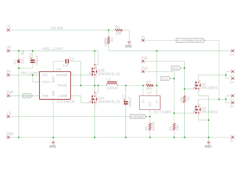
Looking at my archives, it turns out that I've got the schematic for the "battery charge regulator" posted on the interwebs. This used a scheme of just disconnecting the dynamo when the battery was fully charged, although this was done in a pwm sort of fashion.
https://www.flickr.com/photos/kurtsj00/24171993235
The mosfet was a IRF9540 P channel mosfet, which is rated for -100V V_DSS. It is a bit large and pricey for a commercial light. No idea how the commercial lights turn off the dynamo. A cheap relay?? That couldn't be much cheaper than a P channel mosfet, could it?