cryhavok
Enlightened
Tonight I successfully upped the drive current of my wonderful S27-PD. I have zero experience with soldering SMD components, but this mod wasn't too bad.
I always wanted a slightly higher drive current for my S27-PD and I'm the type that isn't happy with something until I have taken it apart completely before putting it back together, hopefully not breaking it in the process...
Looking at the front of the GDx2 board, there is only one familiar (to me) resistor, one .1 ohm resistor (I'm used to seeing 2 on most of Wayne's other boards). I figured that the I=.05/Rsense that Wayne uses on all his boards would be applicable to this board (plus since .05/.1 = 500ma, the drive current of the stock S27). I had some .15 ohm 0603 resistors on hand, so I calculated that if I drop one of those on top of the .1 ohm resistor already in place, I'd get a new resistance of .06 (1/Rtotal = 1/R1 + 1/R2). Plugging this into Wayne's formula, I=.05/.06, I would get a new drive current of 833ma...perfect
So I went ahead and soldered the new resistor on top of the old. Holding my breath, I connected a battery and it worked
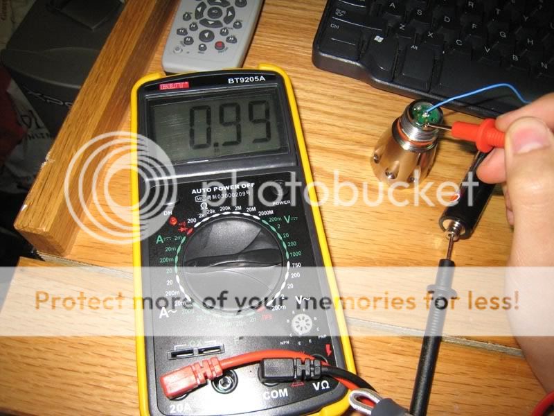
The light pulls ~1A at the battery,

so at least I know the regulation still works and I didn't inadvertently put the light into direct drive (connecting the multimeter to LED leads directly yields a reading of +1.8A)
So I have a question for those of you with more experience measuring with a multimeter (this is the first "real" use of my multimeter I just received from DX). This reading is just the current draw of the battery, not what the led actually is receiving, correct?
Oh, and the results? Lux@1meter has risen from ~4,600 lux@1 meter to ~6,800 lux@1 meter. :rock:
I always wanted a slightly higher drive current for my S27-PD and I'm the type that isn't happy with something until I have taken it apart completely before putting it back together, hopefully not breaking it in the process...

Looking at the front of the GDx2 board, there is only one familiar (to me) resistor, one .1 ohm resistor (I'm used to seeing 2 on most of Wayne's other boards). I figured that the I=.05/Rsense that Wayne uses on all his boards would be applicable to this board (plus since .05/.1 = 500ma, the drive current of the stock S27). I had some .15 ohm 0603 resistors on hand, so I calculated that if I drop one of those on top of the .1 ohm resistor already in place, I'd get a new resistance of .06 (1/Rtotal = 1/R1 + 1/R2). Plugging this into Wayne's formula, I=.05/.06, I would get a new drive current of 833ma...perfect
So I went ahead and soldered the new resistor on top of the old. Holding my breath, I connected a battery and it worked

The light pulls ~1A at the battery,

so at least I know the regulation still works and I didn't inadvertently put the light into direct drive (connecting the multimeter to LED leads directly yields a reading of +1.8A)
So I have a question for those of you with more experience measuring with a multimeter (this is the first "real" use of my multimeter I just received from DX). This reading is just the current draw of the battery, not what the led actually is receiving, correct?
Oh, and the results? Lux@1meter has risen from ~4,600 lux@1 meter to ~6,800 lux@1 meter. :rock:


