Modding the Dorcy 1AAA and SMT techniques tutorial project

Doug S

Flashlight Enthusiast
Joined
Jun 20, 2002
Messages
2,712
Location
Chickamauga Georgia
This thread is intended to show how to do some high benefit modifications to the circuit in the currently available Dorcy 1AAA LED flashlight which has been referred to on these forums as the Gen 3 and/or 4 Dorcy 1AAA. This light has been discussed extensively in this thread:
https://www.candlepowerforums.com/threads/107794
The modifications reviewed in this thread:
https://www.candlepowerforums.com/posts/1804176#post1804176
And the technical details of these mods discussed in this thread:
https://www.candlepowerforums.com/posts/1815020#post1815020
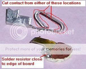
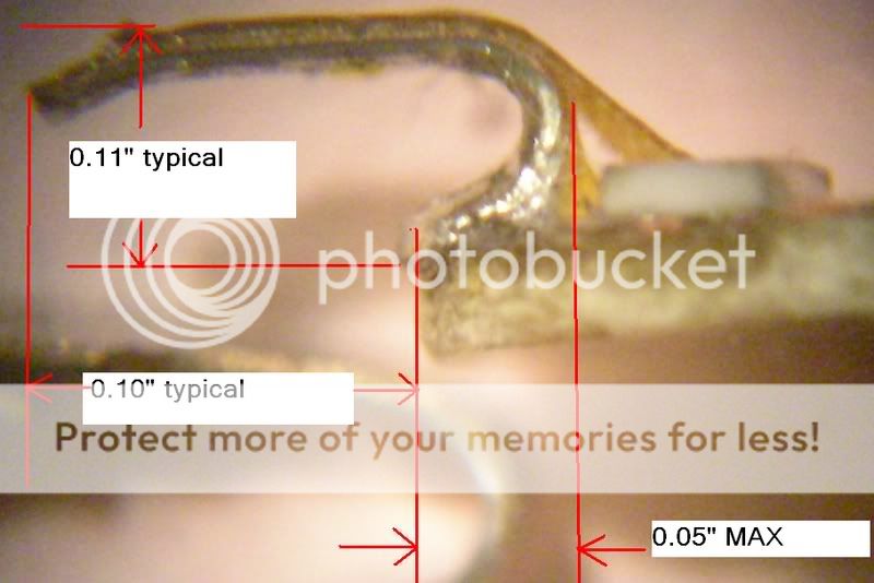
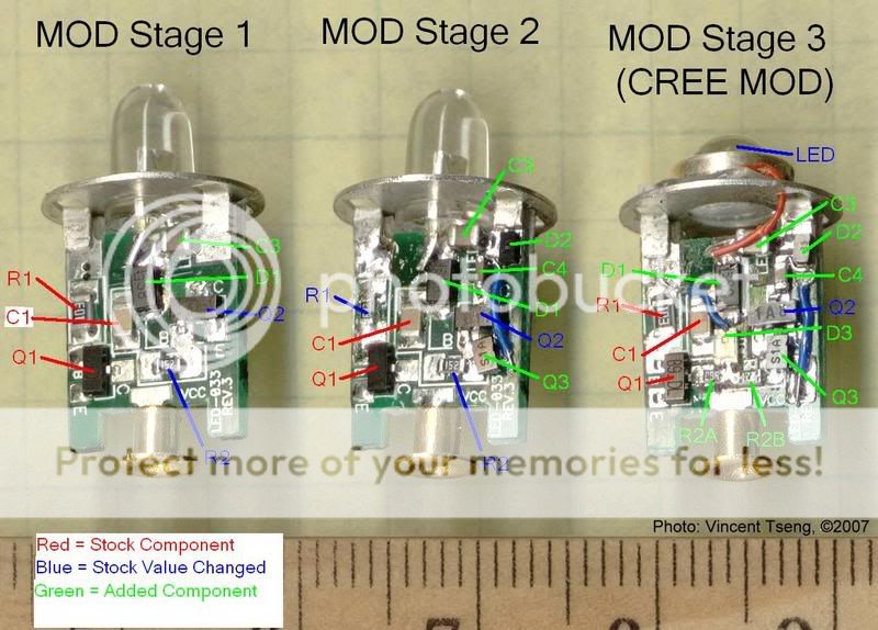
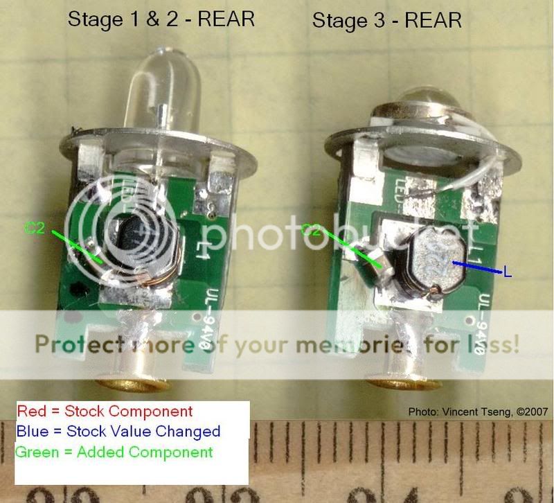
Here are some images of the front and back of the stock circuit board:
DorcyschGEN3Stock-1.jpg


dorcygen3_labeled.jpg


dorcygen3inductorside4mh_small.jpg

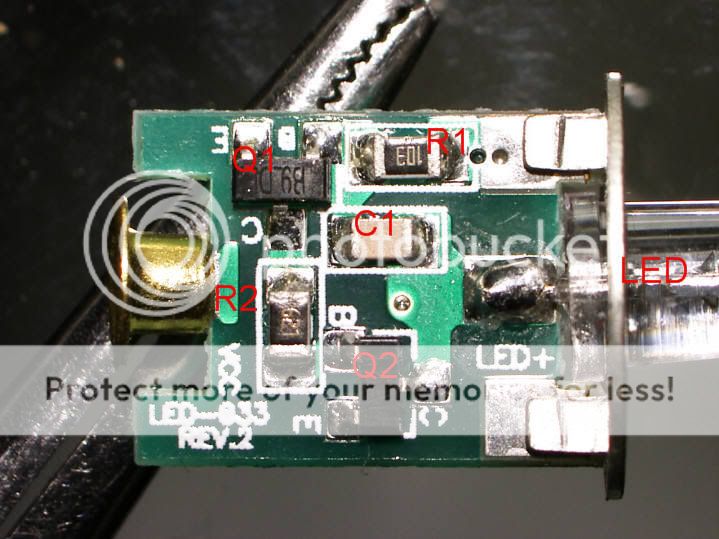
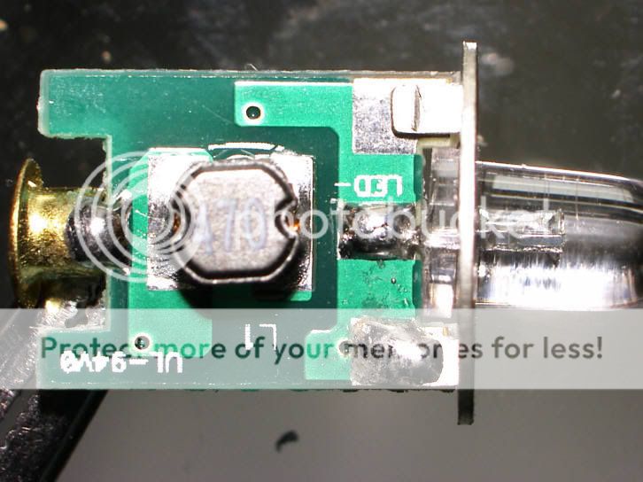
The images directly above were kindly provided by CPF member 1331.
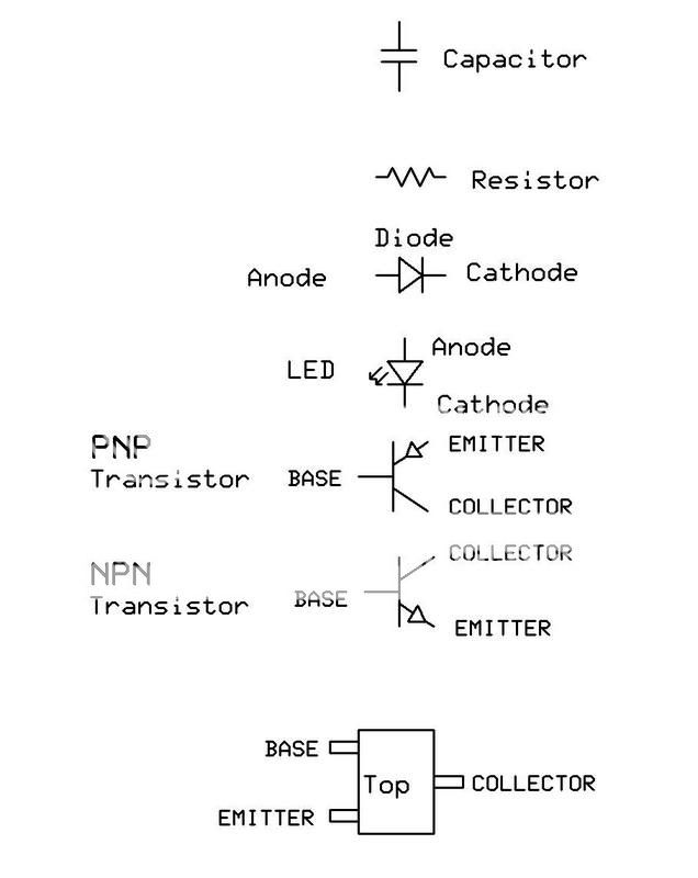
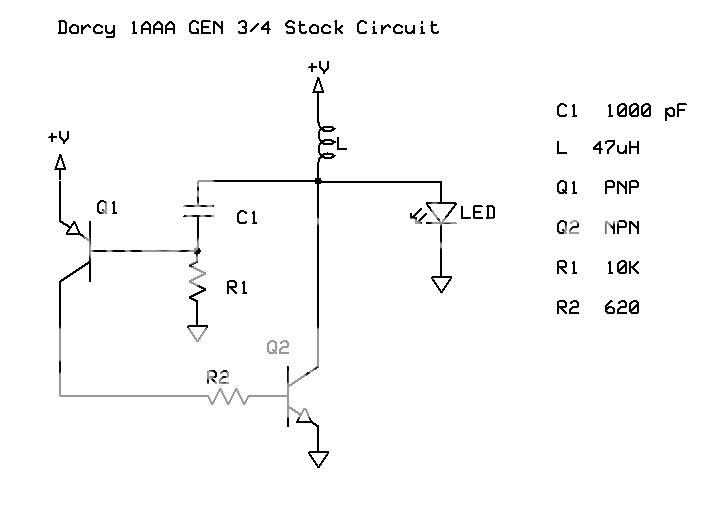
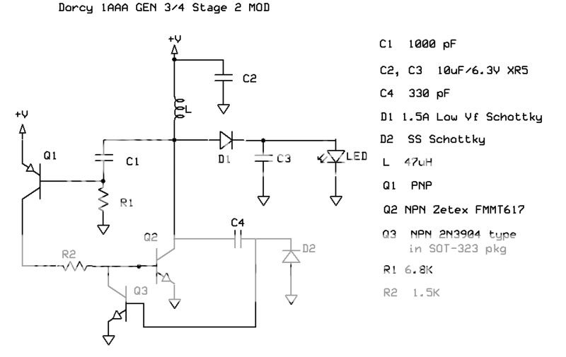
Here are the schematics for the stock circuit as well as the three versions of the mod referred to as stages 1, 2, and 3.
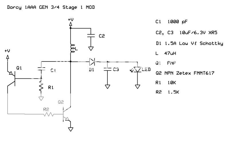
DorcyschGEN3Stock-1.jpg

STAGE 1 MOD:
DorcyschGEN3stage1-1.jpg


STAGE 2 MOD:

DorcyschGEN3stage2-1.jpg

STAGE 3 MOD:
DorcyschGEN3stage3-1.jpg


dorcy1mod_F_Labeled.jpg

dorcy1mods_R_Labeled.jpg

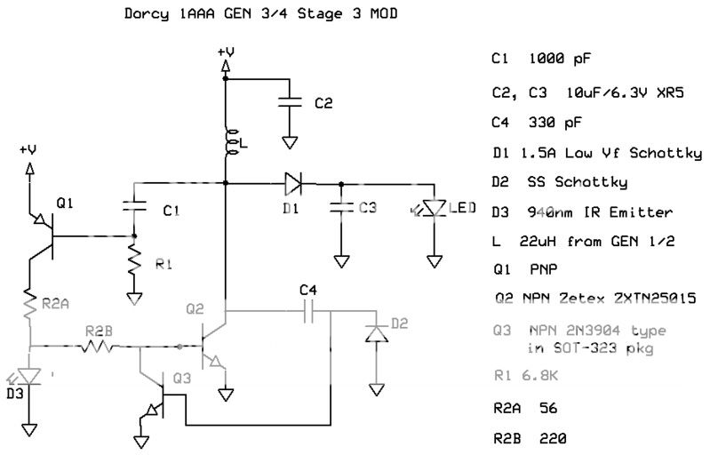
There is no significance to the use of the FMMT617 for Q2 in stages 1&2 and the ZXTN25015 in stage 3. At this point I was experimenting with various Q2 replacements. They are equally good but I think the FMMT617 is more widely available. Here is a link for the FMMT617 datasheet:
http://www.zetex.com/3.0/pdf/FMMT617.pdf
Capacitor C4 for stages 2&3 is listed as 330pF but any value from 100 to 1000pF is fine. In stage 2, R2 is shown as changed to 6.8K but this is not really necessary. It can be left at its stock value of 10K.
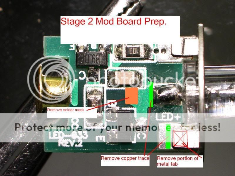
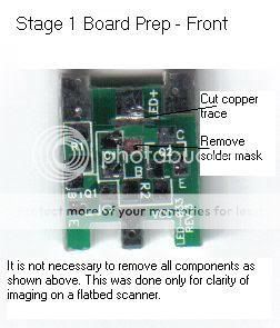
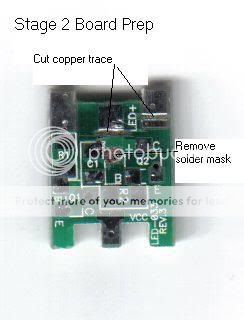
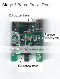
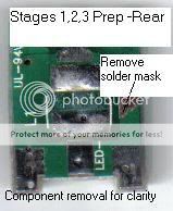
My primary means of reconfiguring the stock board to accommodate the new components is by cutting gaps in the existing copper traces and also scraping away the green solder mask material from the traces to create new locations to which a component can be soldered. Here are some flatbed scanner images of the boards prepped for receiving the new components. Sorry about the image quality. I don't own a camera. For the purpose of making these images, I removed all components. This is not necessary for doing the mods.
DorcyMod_F1_BB_Prep_S1.jpg

DorcyMod_F1_BB_Prep_S2.jpg

DorcyMod_F1_BB_Prep_S3.jpg

DorcyMod_R1_BB_Prep_S123.jpg


For cutting the traces, an Exacto type knife with the smallest blade may be adequate. I prefer and use a #15 scalpel. FWIW, scalpels come in a wide variety of sizes and blade shapes with a standardized numerical nomenclature. I've tried many, I prefer the #15 for this type of work. Here is a link to an Ebay auction that contains a diagram of the scalpel blade types and sizes. This is not an endorsement of this seller. This link for illustration purposes only:
http://cgi.ebay.com/100-Scalpel-Bla...yZ104229QQssPageNameZWDVWQQrdZ1QQcmdZViewItem
Note, that particular auction is for blades only which fit in a reusable handle. More convenient is to buy disposable scalpels which have a handle attached.
The cheapest combination of price plus shipping for small quantities that I've seen is here:
http://cgi.ebay.com/Scalpel-disposa...oryZ3142QQrdZ1QQssPageNameZWD1VQQcmdZViewItem
It looks like if you buy seven the delivered cost is a dollar each. I'd be willing to add this to the group buy a $1/each if one were to evolve from this thread.
The idea of using these modifications as a tutorial project for folks who want to try their hand at modifications that require working with SMT components was discussed a bit in one of the other Dorcy 1AAA threads. All parts that you would need to purchase to do the Stage 2 mod come in at under $5 and are all available from one Electronics catalog retailer, Digikey. There are a couple of complications though if you are not already ordering parts from them for other reasons. There is a $5 surcharge for orders under $25 and shipping will run $5-8 depending on where you are. Also, some of the parts have a minimum purchase quantity of 10. If there is sufficient interest in this to where I likely won't be left holding the bag of parts I don't need, I could do a little mini-group buy of the parts, assort them into ''Kits'', and ship them for on the order of $5-6 for the first kit and well under $5 for a second since about $1.50 of the $5-6 figure includes the postage and packing costs. While this *may* be an inexpensive way to try your hand at working with SMT components, this assumes that you already have the minimal level of tools required. If you need to acquire lots of tools to do this, these could be very expensive lights indeed! On the other hand, you may be the sort that is always looking for a justification for buying new tools. If so, I, as well as others here, can help with recommendations for emptying your wallet on this project. If you have the inclination to buy off of Ebay, you can get an excellent soldering system for less that what some folks around here spend on a single flashlight. That system will still be excellent long after that flashlight is obsolete. How's that for a justification for redirecting some of your expenditures to quality tools?

Here is what I will do. I will keep the discussion of the Electronic/technical aspects of these mods in the thread over in the Electronics subforum. I will keep the step by step ''nuts and bolts'' aspect of doing these mods as well as a bit of tutorial instruction for folks without much/any experience with hand soldering SMT components in this thread. I will include suggestions for minimal level of tools required. Based on this thread, folks can decide whether they want to give it a go and express interest in this thread in the form of ''I'd take a kit'' or ''I'd take X kits'' if done as a group buy. Once there appears to be a critical mass of interest I would start a group buy thread to handle the transaction stuff so that this thread can remain focused on helping folks achieve success doing the actual mods. If there is interest I would be willing to include in the group buy effort a couple of inexpensive tool/supply items that some folks likely would need but are unlikely to be readily available locally or in small quantities [at the moment the two possible items that come to mind are scalpels and SMT solder paste]. Sound reasonable?
I'll follow with a post on tools and techniques. In the meantime, there was a bit of SMT hand soldering tutorial discussion here:
https://www.candlepowerforums.com/threads/149262
 
Last edited:

Doug S

Flashlight Enthusiast
Joined
Jun 20, 2002
Messages
2,712
Location
Chickamauga Georgia
In this post I discuss the minimal and preferred tools to do these mods.
1) You need some method of holding the board securely and also preferrably a couple of inches above your surrounding work surface. There are many things that will work. I personally use a Bessey model S-10 clamp pictured here:
http://www.coastaltool.com/cgi-bin/SoftCart.exe/clamps_vises/bessey/bes10.htm?E+coastest
but something like this should likely work very well too:
http://cgi.ebay.com/2-TOOLMAKER-GRI...0655972QQihZ014QQcategoryZ25297QQcmdZViewItem
The important factors are that either the board or the entire holder can be easily oriented as necessary while working and that it be held securely.

2) You need a soldering tool that has a suitably fine tip. If you have something that has a tip that is at least cylindrical before the actual point, you might be able to fabricate alternate tips by tightly wrapping the existing tip with bare copper wire and filing/grinding the end of the wire to the tip profile you need. I haven't personnelly tried this. *Much* preferred is a quality temperature controlled soldering station with changeable tips. My personal favorite is Metcal but there is other good stuff available. Discussion of what is best can be a bit like those Ford vs Chevy discussions.
3) You need at least one pair of tweezers. If I were to have only one set, it would be a curved tip size 7A. Example can be seen here:
http://cgi.ebay.com/TWEEZERS-ANTIMA...ryZ10363QQssPageNameZWDVWQQrdZ1QQcmdZViewItem
Several sets in different tip sizes and configurations can be handy but not essential. Since they will be holding components while soldering, they need to be metal, not plastic.
4) Small flush cut wire cutters. In a pinch, non-concave nail cutters can be used.
5) Small needle nose pliers.
6) Wire cutter/stripper suitable for small wire. If we do a group buy on this project, this could be optional since I could include cut and stripped wire.
7) Optical aids. While some folks can work with components even smaller than the smallest in these mods with no optical aids, most cannot. What you need will depend on your own circumstance. There has been discussion of this in the following thread:
https://www.candlepowerforums.com/threads/147848&highlight=microscope
Note that member jtr1962 does size 0402 [that's 0.04''x0.02''] with no optical aid. I certainly cannot. The smallest in these mods is size 0603 [that's 0.06''x0.03''].
8) Scalpel or similar. As discussed in the last post, I prefer a #15.
9) Good quality solder wick. My favorite is Chemtronics brand type Rosin SD. Again, if folks want me to, I could just include a few inches with the ''kits'' if we do a group buy.
10) Not at all essential but potentially useful is a rotary Dremel type tool with attachments.

There has been some discussion of soldering technique here:
https://www.candlepowerforums.com/threads/149262
and here:
https://www.candlepowerforums.com/threads/64058
Not mentioned in either of the above two threads is the use of SMT type solder paste instead conventional wire solder. Solder paste dispensed from a syringe and needle onto the component pad prior to soldering makes the task immensely easier. The problem with using wire solder is that you are holding the component with tweezers in one hand, your soldering tool in the other hand, and your third hand is necessary to hold the wire solder. Unfortunately our biological evolution has not kept up with that of technology! Most SMT solder pastes are stencil applied and are too viscous to dispense with a syringe and needle. But there are a few thin enough especially if you cut the needle very short and use 23 or larger gauge. I find that Kester R276 solder paste is suitable. Unfortunately, for most folks a gram or so will last many projects and the smallest unit of sale is a 35 gram syringe for $42 from Digi-key plus you have to pay premium shipping as they consider it a perishable since it is normally stored refrigerated. For our purposes it has a very long shelf life even at room temp. This is another item that I would run a group buy for if I was reasonably assured that I won't get stuck with it. I only go through a few grams/yr myself. What I am imagining here is loading up some syringes with a gram or two, grinding down the needles and providing to whoever needs them. Trust me on this one, dispensing SMT solder paste with a needle is the way to go for hand SMT work.
Next posting I'll address technique a bit for soldering and unsoldering components.
 
Last edited:

Doug S

Flashlight Enthusiast
Joined
Jun 20, 2002
Messages
2,712
Location
Chickamauga Georgia
SMT Soldering Technique.

Desoldering

Make your work area free of clutter. These components are small and hard to find when they decide to jump out of your tweezers. Then you will discover that the cookie crumbs and other debris on your work table look like SMT components. What I do is tape down plain, white paper within a foot of my work area in every direction. It makes those wayward components a lot easier to find.
I like to first remove the excess solder from the leads and pads with solder wick before removing the component. To use solder wick, lay the end of the wick over the area to be cleaned of solder and then press against the top of the wick with your soldering tool. Use the tip in a manner that maximizes the area of the tip in contact with the wick to maximize heat transfer. Once the wick and underlying solder are hot enough, the solder will be drawn into the wick. The solder wick being made of fine copper braid can soak up a lot of heat. If the heat delivery capability of you setup is marginal, it may help to first wet the tip with a bit of solder to aid in heat transfer. You will need to trim off the end of the wick often to remove the portion that is saturated with solder. Removing two terminal components that you do not intend to reuse, you can heat one terminal until the solder on both terminals has melted. At this point you can either push the component off of its pads or pick it up with tweezers. With a three leaded component such as the Q2 transistor, slide the blade of a scalpel under a corner on the side with only one lead, heat the associated pad until the remaining solder on the pad and component lead melt and then lift that side of the component slightly. Repeat on the other side which has the two leads.
A component such as the inductor on the backside of the Dorcy board seen here:
dorcygen3inductorside4mh_small.jpg

can be more difficult. The easy way is to have one of those tweezer type handpieces with two heated tips. Assuming that you don't have the fancy stuff, just use whatever tip you have that is large enough to heat both pads at once. In this case there is nothing to be gained by using solder wick first.
BTW, the inductor does not need to be removed for these particular mods unless you optionally choose to change it which I only suggest if you are really going to jack up the power level by reducing R2 a lot [think NiMh or L92 applications].
After removing all the components that need removing, you may optionally clean up the pads with further use of solder wick. This is mostly cosmetic but it will also permit the replaced and added components to sit more flushly on the pads giving the apperarance of better workmanship. Before adding components I usually clean of the excess flux residues with a toothbrush and heated 91% Isopropyl alcohol. This is optional. Dry with a hair dryer or a few minutes in a warm oven.

Board Prep
Cutting the existing copper traces is done with scalpel or similar tool. Deeply incise the copper with two parallel cuts about 0.01-0.03'' apart and pry out the strip of copper between with the blade of the scalpel. To remove an area of solder mask, lightly incise the margin of the area to be stripped of mask then scrape the area with the blade of the scalpel.

Adding and soldering components
After you have cut traces and removed solder mask, you are ready to add your components. In the case of modifying an existing board as we are doing here, I like to ''dry fit'' all the components by placing them on the board to check their relationship. By doing this, you often can see how slight variations in placement within the bounds of still fitting on the required pads can make things go easier. Once you understand where the components are going, remove them all and get ready to solder. Working one component at a tiime, using a syringe dispense a dab of SMT solder paste at the locations where the component leads will sit on the pads. It does not take a lot of solder. With tweezers, place and hold component. Heat one pad at a time to melt the solder. Apply as much heat as necessary to melt all of the solder and as long as necessary for the component lead to be completely wetted. Beyond this point more/longer is not better. With components with three or more leads you can release the tweezers after the first lead is soldered. With two terminal components such as resistors, capacitors, and diodes which conduct heat well, it is best to start with the terminal which is connected to the greater area of copper trace [which acts as a heatsink]. Once that end is soldered you can usually let go with the tweezers and heat and melt the solder on the other terminal without the first terminal remelting and the component becoming misaligned. Once all components have been added and soldered, visually inspect carefully and touchup any solder joints that look suspicious. Test the board for proper function and then [optional] clean of the flux residues and solder balls with a toothbrush and heated 91% Isopropyl alcohol. Dry with a hair dryer or a few minutes in a warm oven.
Note that all references to optional cleaning assume the use of solder paste or wire solder containing ''No clean'' fluxes. If you are using a water soluble flux [which I don't recommend for novices] you must clean the board thoroughly as these fluxes are corrosive and electrically conductive if moist.
Vapors from fluxes are regarded as unhealthy. Snort as little of the fumes as possible. A small fan in your work area to suck or blow the flux fumes away from you is a good idea.
 
Last edited:

kevinm

Enlightened
Joined
Jun 2, 2006
Messages
891
Location
Denverish
Where were you when I took senior physics (electronics) lab?!?!

This looks like fun! I'd take at least one kit. I went to WallyWorld and bought one of these lights just to do this mod. Will you also include a tutorial for the two stage mod?

Thanks for the great idea and info.

Kevin
 
Last edited:

Doug S

Flashlight Enthusiast
Joined
Jun 20, 2002
Messages
2,712
Location
Chickamauga Georgia
There have been a couple of inquiries about the 2 stage tailcap mod. My primary motivation for starting this thread is to encourage/assist folks in acquiring some SMT soldering skills. I was hesitant to include the 2 stage mod because if you are new to working with SMT, attempting the 2 stage mod likely *will not* be a confidence building exercise. It is a tough one to get right if your skill is limited. That said, for those who already are pretty skilled with SMT or choose to ignore what I have said above, here is the tailcap mod info.
I punched a 1/4'' disc of 0.031 copper clad PCB material. The copper side was divided into two electrical nodes as shown in photo. A spring finger was cut from a Molex KK series 0.156'' spring contact, Molex #08-52-0072. You can actually get two of what you need out of one of these parts. Link below to Molex part drawing:
http://www.molex.com/product/pcb/2478.html
This new finger is to be soldered to the 1/4'' PCB disc. Due to the close clearances involved, there will be a very small area of the finger in contact with the disc. Before soldering, bend the end [last couple of mm] of the finger which will be contacting the Dorcy body tube so that it will be approximately parallel with the surface of the end of the body tube. After the finger is soldered and the geometry looks right, add the resistor to the board. I found that 12 ohms gives a reasonable spread between high and low. The originally 4 fingered plate holding the coil spring must be modified as shown in the photo. It is probably best to remove the coil spring for this operation. The spring can be removed from the 4 fingered plate by rotating the spring CW as viewed from above while pulling gently. It is reinstalled by rotating the same direction but pushing in instead. Where the end of the coil spring touches the PCB disc matters as to providing the best clearance for the new contact finger. Rotate spring in the [now] 3 fingered plate as necessary. All but the end of the new finger must be insulated with kapton tape to prevent shorting to the coil spring and associated 3 finger plate assembly. The tape will adhere better if the spring is cleaned with alcohol before applying the tape. The plastic discs are used as shims to position the height of the PCB. If using 0.031'' PCB I found that around 0.10'' of shims works about right.
Photos below:
TailSwitch4.jpg


TailSwitch3_labeled.jpg


TailSwitchRes_Labeled.jpg


TailSwitch4Res_labeled.jpg


If a group buy evolves from this, I could provided a tailswitch kit consisting of the 1/4'' board, the molex contact, resistor, shims, and Kapton tape for a buck. *Some assembly required*. You'll be on your own. I've already incurred the only significant expense which was the purchase of the 1/4'' punch. I've also got some different thicknesses of PCB material coming to see if there might be a more optimum thickness.
After the first few dozen operations of the installed switch, you should clean the contact and end of the battery tube of some small metal shavings that may be generated as the switch ''wears in''. Note that this mod is best suited to the GEN III and later Dorcies which do not have the slots in the end of the battery tube. The earlier GEN slotted ones may have a problem with the new contact finger hanging up on the slots. If you do try this in an earlier GEN, you may need to chamfer the corners of these slots.

Text and photos added below:

Here are a couple of photos that should help:
TC2.jpg


TC1.jpg

Once again, CPF member 1331 has come to my aid with the above photos. He in fact has addressed my photographically challenged status in more ways than you might imagine.

Note that the resistor is close to the edge of the board. If it is too far towards the center it will contact the three fingered coil spring holder. There are lots of other things that can go wrong with this mod. Here are a few to be aware of:

1) Contact extends too far towards center of PCB and interferes with coil spring holder.

2) Rough edges where the one finger of the 4 finger spring holder was removed may cut thru kapton tape causing short bypassing resistor. You can detect this by measuring resistance from coil spring to end of added contact after assembly. It should measure 12 ohms.

3) The contact to PCB solder joint is a high stress one due to small area. A poor solder joint here will break.

4) Excessive soldering heat causes the copper to delaminate from the PCB.

5) Geometry wrong: lots of possibilities.

While there are lots of ways to get this wrong, the good news is that I have not identified any failure mode that keeps the light from working. You will just have the normal HIGH mode.

Other tips. The particular 1/4" punch that I purchased to make the PCBs is hard on the PCB material. The discs get wedged in the punch and it takes herculean effort to remove them. As a consequence the material may be partially delaminated. Before cutting the copper to create the two nodes on the board, examine the edge of the board for any sign of delamination. If detected, locate the contact finger way from this area.
When cutting the contact from the molex connector, it helps to initially cut the side that will contact the PCB long. This give you something to hold onto when soldering. Once positioned and soldered correctly then cut off the excess.
Beveling the bottom edge of the PCB with an emory board or nail file may prevent it from wedging in the tailcap when test fitting.
 
Last edited:

Doug S

Flashlight Enthusiast
Joined
Jun 20, 2002
Messages
2,712
Location
Chickamauga Georgia
If sufficient interest is expressed here in this thread, here is what the group buy pricing would look like:
Code:
Postage and packing       $1.50 
Stage 2 kit first one        $4.50 
Additional kits:               $4.00 
1g SMT solder in syringe  $4.00 
2g SMT solder in syringe  $6.00 
3g SMT solder in syringe  $8.00 
#15 scalpel                   $1.00 
Two level tailcap kit        $1.00
Included at no charge but only if requested: a few inches of Solder wick, 10 practice SMT components, a bit of practice PCB material, cut and striped 30 Ga wires as required for the connection from D2 to Q3 and for emitter upgrade to a Cree.
Pricing has been designed to insure even dollar totals. I am perfectly OK with mailed cash. Fortunately I live in an area where mail theft, at least at the local level, is not known to be a problem. Paypal option is available for those that prefer it.

The stage 2 kit will consist of all necessary components to do the Stage 2 mod not including the 2 level tail switch mod. The kit will additionally include duplicates of the smallest resistor and capacitor on the chance that you lose one in your shag carpet. It will also include a selection of values of R2 so that you can raise or lower the input power from the stock value.

The tail switch kit will consist of the 1/4'' board, the molex contact, resistor, shims, and Kapton tape.

Note that you could probably do dozens of these mods with 1g of solder paste. I have listed larger amounts if you want it and also because I think that the SMT solder paste will be the deal breaker on this going forward. I already have enough on hand for my personal needs so I don't want to get stuck with a bunch of extra.

Please state in a post to this thread what you would be interested in. Please also state whether you would be willing to purchase a larger quantity of SMT paste than stated, if any, if it will make a difference as to whether this goes forward. Nothing is going to happen on my end unless there is sufficient interest for this to make sense.
I am willing to make this deal with the community. I won't become fabulously wealthy from this group buy should it occur, if you guys keep it as simple as possible for me by limiting the complicating requests for extra lettuce, hold the mayo, etc. I am, however, open to discussion before this actually goes forward about what additional items might be included, power levels that may be desired [determined by value of R2]. etc.
Once there appears that sufficient interest I will order the stuff and post here. If after a month from now it appears that there is not going to be sufficient interest, let's let this thread die a quiet death.
 
Last edited:

1331

Newly Enlightened
Joined
Apr 17, 2005
Messages
58
Doug S,

Thank you for all your work on this. I appreciate the work you have done on deciphering the original board, modifying it, and writing the tutorials. You are one of a few who share and teach skills to readers in the process. Also thanks to UnknownVT and the hours he spent on the results.

I am interested in purchasing:
Stage 2 mod kits 5 ea.
1g Solder paste 2 ea.
Tail cap mod 2 ea.
 

kevinm

Enlightened
Joined
Jun 2, 2006
Messages
891
Location
Denverish
Hey Doug,

I posted above, but to make it official,

1 Stage 2 mod kit 5 ea.
1g Solder paste 2 ea.
1 Tail cap mod 2 ea.

If there is very little interest (like the two of us who have said yes so far), would you consider selling some of your spare parts?

Many thanks,
Kevin
 

PhotonAddict

Enlightened
Joined
Dec 10, 2004
Messages
357
Location
Mtl, Canada
Just noticed this thread. Fantastic post Doug S, especially the SMT soldering tips. Thanks for taking the time to make such a detailed post. :thumbsup:
 

vetkaw63

Enlightened
Joined
Dec 1, 2004
Messages
355
Location
virginia, us
I would be in for 3- stage 2 kits,
2 grams of smt solder paste,
1 #15 scalpel,
3- 2 level tail cap switch,
and some 30 gauge wire that is cut and stripped
Thanks Doug

Mike
 

georges80

Flashlight Enthusiast
Joined
Oct 23, 2002
Messages
1,262
Location
Sunnyvale, CA
Be careful with solder paste (lead and other nasty things). Make sure you clean yourself, your work area and tools used to handle the paste. Keep away from kids/pets etc.

Make sure you have good airflow to move the flux fumes away from you.

i.e. be smart when handling it. Most reputable products (like Kester) have MSDS that you can download and read.

cheers,
george.
 

Doug S

Flashlight Enthusiast
Joined
Jun 20, 2002
Messages
2,712
Location
Chickamauga Georgia
In case the board prep image in the first post is lacking in clarity, I have marked up a good photo provided by member 1331. See below:
dorcygen3_S2_Prep.jpg

Also, for those new to reading schematics, here are the relevant symbols:
Schm_symbols_crop.jpg

The transistors used on this project use the pin assignments as shown at the bottom. BTW, while this is the most common pin assignment for NPN and PNP transistors, it is not universally applicable. Just FYI.
Surface mount resistors if marked, have their value coded as follows: XYZ where X and Y are the first two digits and Z is the number of added zeros. Example: 621 is 62 plus 1 zero = 620 ohms. If an R is used for X or Y it is read as a decimal point and there are not added zeros. Example: 1R2 is 1.2 ohms, R10 is 0.10 ohms.
Ceramic capacitors are usually not marked. Resistors, and also the capacitors used for this project are not directional, e.g., it doesn't matter which direction they are oriented.
Diodes are directional. The cathode end will typically be marked with a line or band.
 

kf4zht

Newly Enlightened
Joined
Jan 28, 2006
Messages
43
Location
Marietta, GA
I have a couple of the kits comming this way but have a quick question, a while back there was a DIY hot air soldering unit that used a solder removing iron and a small air pump. I have the parts lying around to make one, and as I understand it is meant for SMD work. Would this work better than a normal soldering iron?
 
Top