LEDs in a wall light: size of the heatsink?

Cemoi

Enlightened
Joined
Jan 23, 2008
Messages
529
Location
France
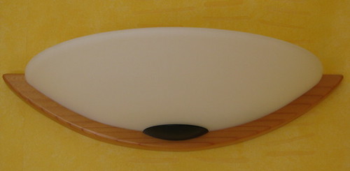
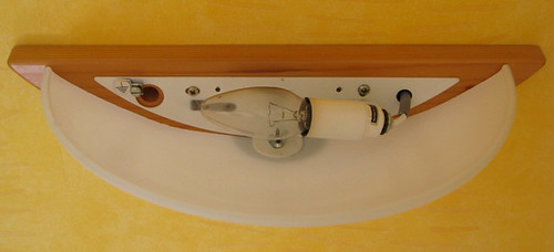
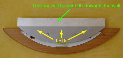
I plan to modify an incan wall light, using a few LEDs.
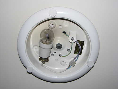
I would thermal epoxy the LEDs (three Cree XR-E Q3 5A driven at 700 mA) on a home made aluminium plate that will fit in the light. The light is not close on top so air should circulate rather well.
Am I correct assuming that the thickness of the aluminium plate is not really important, and that the important factor is the surface of the plate in contact with the air?
What minimum surface should this aluminium plate be?
 

SafetyBob

Enlightened
Joined
Oct 20, 2007
Messages
766
Location
Yukon, Oklahoma
Could you give us a picture of the light you are trying to modify? And how often do you plan on leaving the light on?

Question number two: Are you against fan cooling if small size is of the upmost importance?

Question number three: Who's transformer or by what method are you actually powering the leds with?

You might also go the the Beyond Flashlights, General Light Discussion, Fixed Lighting forum and have a look around too. There have been a number of us that have done this.

Bob E.
 

Cemoi

Enlightened
Joined
Jan 23, 2008
Messages
529
Location
France
Thanks Bob for your questions, which I will try to answer below.
I'l provide pictures in a couple of days (got the camera, but the memory card reader is at my office).

how often do you plan on leaving the light on?
Constant on for one hour (summer) to four hours (winter) per day, plus say twenty times on for one minute (entering the room to fetch something, and switching off the light when exiting) per day.

Are you against fan cooling if small size is of the upmost importance?
I'd rather keep it simple, especially for my first fixed lighting upgrade.

Who's transformer or by what method are you actually powering the leds with?
I currently have this cheap CC supply from DX, but it gets quite hot when powering three LEDs.
I have ordered better ones from led-tech.de: one for 3 to 4 LEDs, and one for 5 to 8 LEDs.

You might also go the the Beyond Flashlights, General Light Discussion, Fixed Lighting forum and have a look around too.
I did consider starting this thread in the FL forum, but saw that it is far less active than Homemade and Modified Lights. Since my project is definitely about a homemade modified lights, I thought I would get more attention in the very active HML forum. Your quick and detailed answer backs up my choice ;).
 

mitu

Newly Enlightened
Joined
Nov 10, 2008
Messages
4
Location
Finland
I would thermal epoxy the LEDs (three Cree XR-E Q3 5A driven at 700 mA)...

What minimum surface should this aluminium plate be?

Vf=3.5V(from spec), I=700mA -> 2.45W

Help from internet:
http://www.daycounter.com/Calculators/Heat-Sink-Temperature-Calculator.phtml
With Rj-a=8 and max tjunc 80C it leads to abt 14C/W heatsink...


And again some help:
http://www.frigprim.com/online/natSinglePlate.html
It helps you to find suitable size...

And of course you should add some extra to be at safe side...
And my example is for one led only. I quess max temp for cree led is
150C if size is critical but it might toast your led... Even 80C from cree
reliability manual sounds high too, I would go far below that and
propably verify the results with other calculator(s)... :eek:oo:


MiTu
 

Cemoi

Enlightened
Joined
Jan 23, 2008
Messages
529
Location
France
Thanks Mitu for the links.

Help from internet:
http://www.daycounter.com/Calculators/Heat-Sink-Temperature-Calculator.phtml
With Rj-a=8 and max tjunc 80C it leads to abt 14C/W heatsink...
I assume "Rj-a=8" is the "junction to solder point" given in the Cree XR-E spec sheet. So I put in in the "Thermal Resistance - Junction to Case" field of the calculator.
Max ambient temp = 25°C, Max junction temp = 80°C, but then if I put 2.45 in the Power field and click Compute I get a Junction Temperature in the field on the left, not a thermal resistance.

And again some help:
http://www.frigprim.com/online/natSinglePlate.html
It helps you to find suitable size...

This would be quite useful for my applications, but unfortunately this web pages doesn't work with both Safari and Firefox ("exception: java.lang.NumberFormatException : empty string") :(

Even 80C from cree reliability manual sounds high too, I would go far below that
How much?
 

mitu

Newly Enlightened
Joined
Nov 10, 2008
Messages
4
Location
Finland
Thanks Mitu for the links.
I assume "Rj-a=8" is the "junction to solder point" given in the Cree XR-E spec sheet. So I put in in the "Thermal Resistance - Junction to Case" field of the calculator.
Max ambient temp = 25°C, Max junction temp = 80°C, but then if I put 2.45 in the Power field and click Compute I get a Junction Temperature in the field on the left, not a thermal resistance.

So true... I did it by 'guessing' the heatsink rth (thermal resistance 1) by computing which value gives 80°C to tjunction...
Here is one more: http://changpuak.ch/electronics/calc_23.html (pad=0)


This would be quite useful for my applications, but unfortunately this web pages doesn't work with both Safari and Firefox ("exception: java.lang.NumberFormatException : empty string") :(
How much?

Possible, it is some kind of java applet... But it is very cool one, it allows you to turn plate horizontal or vertical etc. May be this gives an adequate guess:

http://highfields-arc.6te.net/constructors/olcalcs/heatsurf.htm

How much?

Well, your space might be the limit. By halfing the rth of the heatsink gives tj of 62°C, but means four times more area.
Of course you cannot get lower than 45°C at the junction due to that 8°C/W Junction to Case resistance. I would use all available space, if that is easily possible... At least if it can be done with flat aluminium plate.

MiTu
 
Last edited:

Cemoi

Enlightened
Joined
Jan 23, 2008
Messages
529
Location
France
I did it by 'guessing' the heatsink rth (thermal resistance 1) by computing which value gives 80°C to tjunction...
Here is one more: http://changpuak.ch/electronics/calc_23.html (pad=0)
OK, it is clear now.
The second URL gives the same result, great.

To achieve Rth=14°C/W, a 13 cm2 plate is required.

But I will be using three LEDs. Can I simply multiply this surface by three?

I tried to enter the total power for three LEDs (about 7.5W) in the calculator but this gave me a negative value for Rth. I assume this is because of the 8°C/W value for the junction to case resistance, but I'm probably wrong trying to sum up powers this way.
 

mitu

Newly Enlightened
Joined
Nov 10, 2008
Messages
4
Location
Finland
But I will be using three LEDs. Can I simply multiply this surface by three?

I would do that... :cool:

Theory perhaps is not that simple but if you are at safe levels I guess that is close enough.
Just led at centre of square heatsink, times three...


I tried to enter the total power for three LEDs (about 7.5W) in the calculator but this gave me a negative value for Rth. I assume this is because of the 8°C/W value for the junction to case resistance, but I'm probably wrong trying to sum up powers this way.

It is not propably that easy... 8°C/W is only for one led, don't know how it should be calculated... :hairpull:
 
Last edited:

Cemoi

Enlightened
Joined
Jan 23, 2008
Messages
529
Location
France
Here are the pictures:

My wall light seen from the bottom:
3441368787_59424af6b8.jpg


The inside, seen from the top:
3442183124_1e57664f64.jpg


It is attached to the wall about two meters above ground, so no risk to blind people even if the LEDs are set flush with the top of the frosted glass part.

The aluminium plate I have made, installed on the light (frosted glass part removed):
3441369103_237dd52c85.jpg

I left about one centimeter between the lower edge of plate and the frosted glass part, to allow for air flow. For the same reason, I would leave a few mm clearance between the aluminium plate, and the white metal plate.
The top part (lighter on the picture) would be bent so that is not visible from a distance.
 

VidPro

Flashlight Enthusiast
Joined
Apr 7, 2004
Messages
5,441
Location
Lost In Space
that is nice with the open air, and you will get a bit of convection turbulance with the vertical. what did you need all the math for :) you only got so much available space, unless you wanted to "fold" it back down again, for 2x the sheet size
700ma run, instead of a high overdrive, should work good, so where you gonna stuff the driver ?

love them pictures.

if you werent getting enough cool , you could always spacer the frosted shade out a few MM and increase the convection flow behind there, and any reduction in drive current , would drastically change the cooling needs.
but heck is good now not like a CLOSED up thing like many other fixtures are.
dont close the sync sheet top against the wall tight, so you maintain the heat rises airflow that will occur.
 

Cemoi

Enlightened
Joined
Jan 23, 2008
Messages
529
Location
France
what did you need all the math for :)
Because I had absolutely no idea of the required size for a heatsink.
But I assume the figures above given by the calculators (minimum surface) greatly depend on how the air can flow around the heatsink ?

700ma run, instead of a high overdrive, should work good, so where you gonna stuff the driver ?
My driver(s) all run at 700 mA. And my LEDs are neutral white XR-E so the max specified current is 700 mA.
I'll probably put the driver at the bottom of the plate, but not touching it. Easy to stuff if I use the tiny DX one, more difficult with the LED-tech.de which is twice as big.

if you werent getting enough cool , you could always spacer the frosted shade out a few MM
Good idea, but not easy to implement: the frosted shade rests on the wooden part, and is held only by one central screw at the bottom. I could easily drill another hole (further away) in the metal part holding it, but I would need some means of stabilizing the shade.

but heck is good now not like a CLOSED up thing like many other fixtures are
This is the easy one to start with. I'll soon post pictures of another (closed) ceiling light, which will be another kettle of fish.:thinking:
dont close the sync sheet top against the wall tight, so you maintain the heat rises airflow that will occur.
Of course, I plan to leave at least 5 mm clearance between the plate and #1 the wall, #2 the top of the wooden part.

Now an additional question: I plan to use no optics on the LEDs to get maximum brightness. All LED MCPCB will be placed vertically on the plate. Do I need to protect them against dust? I could use a small Perspex strip fastened to the top of the bent part of the aluminium plate, but this would affect the airflow.
 

VidPro

Flashlight Enthusiast
Joined
Apr 7, 2004
Messages
5,441
Location
Lost In Space
yup you got a little chimney there, so its much more heat removal.

you said cree, they have a glass dome, not the gelly silicoln dome (which can hold dust), so potentially they are more cleanable, but even silicoln gel domes can be cleaned.
dust protection vrses full cleaning would be relative to other stuff getting in the air, that would stick to the dome and require cleaning anyways.
little open half moon dust domes over the led star area itself wouldnt hurt your total cooling package much, then you still gotta clean them too?
 

Cemoi

Enlightened
Joined
Jan 23, 2008
Messages
529
Location
France
little open half moon dust domes over the led star area itself wouldnt hurt
Good idea, I'll have to find a source for these.

Now here are the pictures of my second project, a closed ceiling light in my bathroom:

Bottom view, with the frosted shade:
3445354294_bc8ac3c5df.jpg


Inside view, after removal of the frosted shade:
3445354424_cd9850c3a1.jpg


The body of the light is painted sheet metal.

My plan for this one is to have an aluminium disk machined, exactly the internal size of the light body. I would fasten in halfway up inside the light body, and put some thermal compound all around to allow heat transfer from the aluminium plate to the sheet metal.
The driver would be placed above the aluminium plate, and the LEDs on the bottom of course.
Comments on this general design would be welcome.
I'm specially wondering if the heat transfer would work well enough. I might drill holes in the sides of the sheet metal body to allow some air flow but since this is in a bathroom I'm a bit concerned about humidity getting in (no liquid water flowing, but possible condensation from hot water vapor).
 

VidPro

Flashlight Enthusiast
Joined
Apr 7, 2004
Messages
5,441
Location
Lost In Space
machined? dont they give you tin snips :)
how many leds you plannin on stuffing in this one? me i would do like 10 at about 500ma, or 10 at 350ma and that would be just about enough light. if your going to be running this for thousands of hours , as the time adds up when you think 10 years, your going to want to go low and slow , and not to thier "max drive" or put Quad Die crees in, ohh the warm ones, then you have 4emitters per led unit, and can run each at normal 350.

was the original bulb 40w or 60? and was it enough light in the location?

how could you rollup the backside of sections of the aluminum, then affix it to the steel fixture at say 5 points, use washers to get lots of aluminum to steel connection AND still the large aluminum surface too.
say have holes in the main plate for the screwdriver.
like cut out a "star" type shape, then backroll the 5-6 star end triangles that will attach and transfer some heat back to the fixture.

moisture , and there is a lot of it if its a nice hot shower, would effect the driver most, silicoln sealers and silicoln sprays will stop oxidations, a very light spray of something like liquid wrenches silicoln spray (the solventy kind) could protect any exposed metal stuff for a long time, the soldered connection would have thier own tin cover via the solder.

hmm that cap seems to seal really well, how the heck were they cooling the wattages that was already in it? it looks like it was already getting hot in there from the bulb. all our closed incan fixtures have air gaps somewhere at the top for escaping heat to leave, this looks more like something for a circle florescent cooler bulb, with a balast on the metal to cool it.

holes in the side, then where does the air come in? is the dome glass?
 
Last edited:

VidPro

Flashlight Enthusiast
Joined
Apr 7, 2004
Messages
5,441
Location
Lost In Space
Good idea, but not easy to implement: the frosted shade rests on the wooden part, and is held only by one central screw at the bottom. I could easily drill another hole (further away) in the metal part holding it, but I would need some means of stabilizing the shade.

.

ahh i got it, FEET, you know those little rubber feet to stick on things, and rubber/silicon bumbers , we use a lot of those and always have many sizes ready to stuff in places to shim things up. they have a nice clear ones too, something like that could be used to go between the wood and the fixture frame, the Beump will seperate and/or hold , but take up very little space or change the look. just a gripping almost invisable shim.
 

Cemoi

Enlightened
Joined
Jan 23, 2008
Messages
529
Location
France
machined? dont they give you tin snips
I plan to use a rather thick plate (at least 3 mm) to ensure a sufficient contact surface between the aluminium and the steel.
how many leds you plannin on stuffing in this one? me i would do like 10 at about 500ma, or 10 at 350ma
I already have my driver (700 mA) so this is set. I was thinking of three LEDs, adding an additional one if it is not bright enough. It is a very small bathroom, and there is another, very bright light (a 18 W fluorescent strip).

if your going to be running this for thousands of hours (...) your going to want to go low and slow
One hour a day maximum, i.e. less than 400 hours a year, 4000 hours after ten years, so far below the lifetime of an LED, and maybe (?) well before they start dimming.

was the original bulb 40w or 60? and was it enough light in the location?
60, a bit dark, so I'd like a bit more light but not much.
rollup the backside of sections of the aluminum, then affix it to the steel
good idea, but more difficult to make, and I'm not sure that the contact surface will be greater than that of a 3 mm thick plate contiguous to the steel on all its circonference.

hmm that cap seems to seal really well, how the heck were they cooling the wattages that was already in it? it looks like it was already getting hot in there from the bulb
I never worried about this. It may get hot, but the top of the steel casing is flush with the concrete ceiling that may act as a massive heatsink.

holes in the side, then where does the air come in?
In the steel casing, cooling the plate.

Re. the wall light:
little rubber feet to stick on things (...) could be used to go between the wood and the fixture frame
:twothumbs thanks for the suggestion. In the meantime I realized that there is a bit of play in the fastening hole of the frosted shade, allowing me to move it away from the wood by a couple of mm. Not much, but may well improve the air flow, and with your suggested rubber feet the shade will be quite stable.
 

VidPro

Flashlight Enthusiast
Joined
Apr 7, 2004
Messages
5,441
Location
Lost In Space
well with that driver i would plan on 4 minimum, not 3, then it will be about as bright as a 16-18W type of florecent, actually only about 12w relative BUT, with the led you have the huge advantage of the light only going where it is USEFULL.
so not much of the light will be boucing around to the top of the fixture not getting out.

and yes 4000 aint squat for time, so driving at the 750 wouldnt be an issue, by 10 years things will change anyway :)
 
Last edited:
Top