A question concerning 7135 chips

tx101

Flashlight Enthusiast
Joined
May 17, 2008
Messages
2,357
Location
London UK
With the SST-90 and SST-50 emitters becoming available
I am looking for a low cost board/s to drive them.
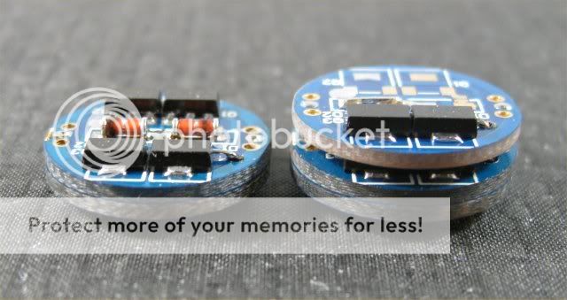
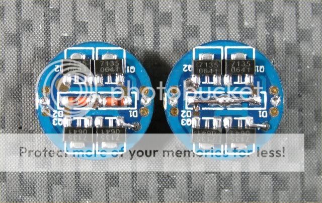
Since I have a draw full of 7135 boards, my question is,
is there any limit to how many 7135 chips wired in parallel
to drive a SST-90/SST-50

Example, I have the following, 1 x 8 7135 (2.8A), 1 x 3 7135 (1A)
and 1 x 3 7135 (1A) with multi levels. Can these all be wired up together
to drive a SST-50 at 4.8A ?


Thanks
 

jar3ds

Flashlight Enthusiast
Joined
Sep 12, 2005
Messages
1,988
Location
USA
i think so as long as you only give the boards 4.5v max... i have plans to do something like this too... so i'd love to hear more input!
 

bshanahan14rulz

Flashlight Enthusiast
Joined
Jan 29, 2009
Messages
2,819
Location
Tennessee
I think you can hook as many up as you want. If your battery can't provide the amps via DD, though, they won't be able to with a 7135. I think of it as a current limiter device. At least, that's my understanding.
 

Mettee

Enlightened
Joined
Aug 5, 2008
Messages
678
Location
Arizona
I have seen a picture from download or netkids where they have 9 amc boards stacked up. they did confirm that it worked, and it was an experiment because another driver did not exist at the time they created it that would do the job.
 

csshih

Flashlight Enthusiast
Joined
Sep 21, 2008
Messages
3,950
Location
San Jose, CA
there shouldn't be an issue, I'd suspect.
though.. what are you running it on? (gonna guess it's going to fall out of regulation very early on)

edit :ohgeez: ssts are pretty low Vf.. it's gonna be nice and regulated for a long time.
 

jar3ds

Flashlight Enthusiast
Joined
Sep 12, 2005
Messages
1,988
Location
USA
I have seen a picture from download or netkids where they have 9 amc boards stacked up. they did confirm that it worked, and it was an experiment because another driver did not exist at the time they created it that would do the job.

:twothumbs
 

tx101

Flashlight Enthusiast
Joined
May 17, 2008
Messages
2,357
Location
London UK
there shouldn't be an issue, I'd suspect.
though.. what are you running it on? (gonna guess it's going to fall out of regulation very early on)

edit :ohgeez: ssts are pretty low Vf.. it's gonna be nice and regulated for a long time.

IMR 26500
 

darkzero

Flashaholic* ,
Joined
Oct 7, 2003
Messages
4,459
Location
SoCal
Yes it will work. bshanahan14rulz is right, if your battery can not deliver the target current it won't with the 7135s hooked up.

I made a few a while back & put them up for sale. I made some with 10x AMC7135s. Problem is with only 1 li-ion it would not deliver even 2.8A with a single li-ion cause of the voltage drop. with 4 NiMhs it did but the chips got very hot cause thet were over spec. Not sure how they perform with IMRs though since IMRs were not available then & I haven't used any since then.

8x 71235s & 10x 7135s
Img_2592.jpg


Img_2595.jpg
 

Al Combs

Enlightened
Joined
Jul 2, 2007
Messages
872
One thing I was wondering about. I found out from this thread the DX.6190 uses an ATtiny13V-10SSU RISC processor. I guess the others are using a similar type processor if that's not the board you had in mind. I have no idea how this controls the output from a bunch of 7135's. But since the LED+ output is picked up from the Atmel chip and not the Vdd lead of the 7135 chip, doesn't that mean the 4.8 amps is going through the trace of the multi-mode board? Even if the chip can handle that much power, the traces on those 17 mm boards are really tiny. A stack of single mode boards would definitely work. There you have the choice to pick up the power from the wire you use to make the parallel connections. Since DX is selling those multi-mode boards for $3.19, it seems like an acceptable risk.

I think the battery will be fine. I use a single IMR26650 in a P7 Mag2C. I bought a DSVNI P7 from PhotonFanatic. With a pair of 1,400 ma 7135 boards I got from DX, it delivers 2.82 amps just like I was hoping. The voltage across the LED was only 3.28 volts. It is almost an H bin. I'm sure that's a big help as far as staying in regulation. I also removed the reverse polarity diodes from the DX boards. When it seemed to be ever so slightly dimmer I measured tailcap current as ≈ 2.5 amps. The battery voltage at that point was about 3.6 volts. One of the things I like about an unprotected battery in this setup is you would easily notice it dropping below 3 volts.

I think the SST-50 take a little more voltage to reach full power. Guesstimating from the current vs voltage graph on page 9 of the Luminus docs on the SST-50, it takes 3.53 volts to reach 4.8 amps. So its Vf is a little higher than my P7's. Then again that same graph in the P7 docs say I need 3.61 volts to reach 2.8 amps. They haven't changed that graph since the J bins. I guess it really depends on the luck of the draw with the LED you get.

I used your idea DZ of drilling through the board from the sales thread I first saw that picture in. I used a #60 drill hole to run a 20 gauge resistor lead to make the parallel connection. It looks so much neater than a wire looping around the edge of the board. Thanks for the idea!:wave:
 

tx101

Flashlight Enthusiast
Joined
May 17, 2008
Messages
2,357
Location
London UK
Thanks for all the input guys lovecpf

I was already thinking that using 7135s at such a high current
could cause issues with heat. I guess I will mount the boards
on a couple of Sharksinks (component side down)

To be on the safe side, I will take your advice Al Combs and
do away with the multi-output board and replace it with a
plain-Jane 7135 board .... Yes, I known $3.19 is cheap BUT
they take forever to ship :D

BTW, I received a Britelumens SST-90 HS this morning :party:
all I need now is to cannibalize one of my Mag builds to get
the host :whistle:
 

jar3ds

Flashlight Enthusiast
Joined
Sep 12, 2005
Messages
1,988
Location
USA
use the d2Flex for your dimmer... use the 7135 to limit current :D
 

tx101

Flashlight Enthusiast
Joined
May 17, 2008
Messages
2,357
Location
London UK
use the d2Flex for your dimmer... use the 7135 to limit current :D

Hmm ... thats a good idea, now if only I had a spare one :(
Do you know if this combination will actually work ?

To be honest, this build is more of an experiment to see if it will
work. If it does then I was planing to get the more manageable
SST-50 and build a light with a Fivemeg blood red 1C that is on the
way to me :D
 

Mettee

Enlightened
Joined
Aug 5, 2008
Messages
678
Location
Arizona
I used your idea DZ of drilling through the board from the sales thread I first saw that picture in. I used a #60 drill hole to run a 20 gauge resistor lead to make the parallel connection. It looks so much neater than a wire looping around the edge of the board. Thanks for the idea!:wave:

I wondered if I could do that the other night, glad to see the drill idea works well.
 
Last edited:

Al Combs

Enlightened
Joined
Jul 2, 2007
Messages
872
use the d2Flex for your dimmer... use the 7135 to limit current :D
From the TaskLED site, "Maximum drive current 3.4A (70C ambient) or 4.5A (25C ambient)". Here is a post from George himself in a cmacclel thread that there is apparently a new version D2Flex that can handle 10 amps. If you want to get a D2Flex, maybe you should email TaskLED first to make sure you get the right one. If you look at the top of this thread, cmacclel says he used a D2Flex with no regulator on an SST-50 with a BatterSpace 26650. I'm not sure if these are IMR's as they have a max discharge of 10 amps. It might behave differently with the AW IMR26500's. Here's a post from moviles using a pwm (unregulated) dimmer from an MTE SF-15. He says the FET handles 71 amp. I guess that should be enough.
 

Al Combs

Enlightened
Joined
Jul 2, 2007
Messages
872
I used your idea DZ of drilling through the board from the sales thread I first saw that picture in. I used a #60 drill hole to run a 20 gauge resistor lead to make the parallel connection. It looks so much neater than a wire looping around the edge of the board. Thanks for the idea!:wave:

I wondered if I could do that the other night, glad to see the drill idea works well.
I got a little close to the ground ring on one of the boards. It was easy to trim away some of the copper with a #11 X-Acto blade.
 

Justin Case

Flashlight Enthusiast
Joined
Mar 19, 2008
Messages
3,797
Right. You want to use a very small drill bit that fits in-between the outer ground trace and the center anode pad. I've also used a #60 (0.040") bit. I wouldn't use any drill bit size larger than that.
 
Last edited:

darkzero

Flashaholic* ,
Joined
Oct 7, 2003
Messages
4,459
Location
SoCal
I used your idea DZ of drilling through the board from the sales thread I first saw that picture in. I used a #60 drill hole to run a 20 gauge resistor lead to make the parallel connection. It looks so much neater than a wire looping around the edge of the board. Thanks for the idea!:wave:
I got a little close to the ground ring on one of the boards. It was easy to trim away some of the copper with a #11 X-Acto blade.

:twothumbs


Carbide drill bits for use on PCBs work best for this. You can get the resharpened ones on ebay or Harbor Freight for cheap.
 

Al Combs

Enlightened
Joined
Jul 2, 2007
Messages
872
Hmm, carbide makes sense drilling through glass. I had a regular HSS #60 handy at the time. But even if I had thought of carbide, I don't think I would have had enough patience to wait for the mail.:crackup:

Thanks again Will.:wave:
 

StefanFS

Flashlight Enthusiast
Joined
Oct 12, 2006
Messages
1,262
Location
Silicon Road 1, Sweden
Thanks for all the input guys lovecpf

I was already thinking that using 7135s at such a high current
could cause issues with heat. I guess I will mount the boards
on a couple of Sharksinks (component side down)

To be on the safe side, I will take your advice Al Combs and
do away with the multi-output board and replace it with a
plain-Jane 7135 board .... Yes, I known $3.19 is cheap BUT
they take forever to ship :D

BTW, I received a Britelumens SST-90 HS this morning :party:
all I need now is to cannibalize one of my Mag builds to get
the host :whistle:

The ATMEL chip used for multimode on the 7135 boards get less than a few mA (much less if I remember correctly). Well within specs. The ATMEL on my two level 7135 boards survive in my 3xP7 Mags powered by 3 x D-size LiION. I've also been overdriving a 4x CREE R2 setup running it at 5A for a long time without problems.
 

Latest posts

Top