I figured I would do a write up on this build. I have been around the site for a while and have been modding a lot of lights in the background. I just dont find the time to post up a thread on the builds, but I figured I would give it a try.
I did some research on parts I wanted to use and had a good idea of what I was going to do. I wanted to use DerWitchtels new improved heat sink because I knew it would help with keeping things cooler. It extends down deeper into the mag body and allows a place to attach the drivers. I had some questions on what reflector to use so I asked DerWitchtel and he was able to give me enough info to decide to use the older style MCE reflector, which turns out to be a great combo with the SSR-50.

The first thing I had to do was to fit the leds to the heat sink. This required removal of about .020 from the bottom of each star. I did this over the course of a few days it was tedious work. I had one lost soul, you can see there in the background

Glued LEDs in place with AA.

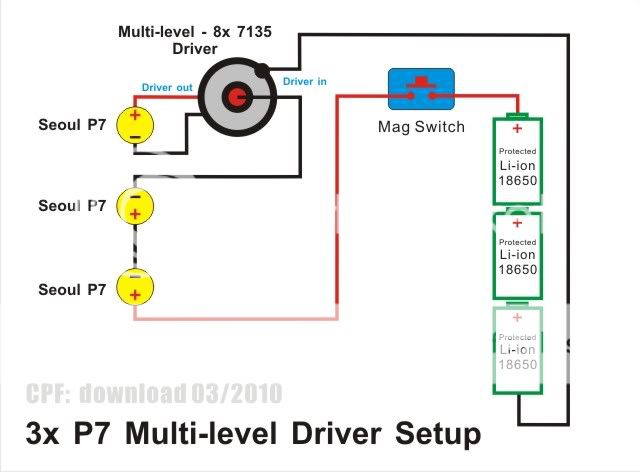
Next part that I worked on was the regulation for this light. I decided to use an AMC board set up to provide about 4.2a with 3 modes.

And I was able to use 20 gauge wire...

Things in place in the back, later I potted them in place with some clear epoxy.

I have not seen too many people use the new style switch so I thought I would post a pic of how I made battery contact. Modding the rest of the switch is the same for clicky or momentary. A small hole is drilled first, then with that metal piece out I place a small nut inside it and re-install it in the switch housing. Once its back in place I screw the brass screw in through the hole into the nut. Worked out great.


Then I worked a little more on the business end. Soldering was tough with the heat sink sucking away all the heat I wish they had turned out better but I think they are still good.

Once I was done here I wired the switch and tested things....its alive...on low.

Cleaning and assembly. Getting rid of the dust.

Reflectors in. ETA: I did remove material from the bottom of the reflector to allow the wires to pass better and to make
sure there were not any shorts. There were no problems but I wanted to make sure.

That is the majority of the wiring. For the battery holder I used a simple piece of PVC because it works very well. I added an o-ring to help keep the holder in place while changing batteries. Both ends are cut and a chamfer is placed on the ID with the lathe. Nothing special.

I also plan on an 18650 PVC holder made from solid stock, I just have to pick that up.
Tail cap has been modded and shortened, we have all seen enough of that. I did add a small Al pill to the spring to protect the battery.
All finished up with UCL lens. Saw the smudge in this pic and went back and cleaned it off.

Sorry to those of you who saw this thread early, it posted and I am not sure why...then when I went to fix it I got bit by the great and awesome "Vista"
I did some research on parts I wanted to use and had a good idea of what I was going to do. I wanted to use DerWitchtels new improved heat sink because I knew it would help with keeping things cooler. It extends down deeper into the mag body and allows a place to attach the drivers. I had some questions on what reflector to use so I asked DerWitchtel and he was able to give me enough info to decide to use the older style MCE reflector, which turns out to be a great combo with the SSR-50.

The first thing I had to do was to fit the leds to the heat sink. This required removal of about .020 from the bottom of each star. I did this over the course of a few days it was tedious work. I had one lost soul, you can see there in the background

Glued LEDs in place with AA.

Next part that I worked on was the regulation for this light. I decided to use an AMC board set up to provide about 4.2a with 3 modes.

And I was able to use 20 gauge wire...

Things in place in the back, later I potted them in place with some clear epoxy.

I have not seen too many people use the new style switch so I thought I would post a pic of how I made battery contact. Modding the rest of the switch is the same for clicky or momentary. A small hole is drilled first, then with that metal piece out I place a small nut inside it and re-install it in the switch housing. Once its back in place I screw the brass screw in through the hole into the nut. Worked out great.


Then I worked a little more on the business end. Soldering was tough with the heat sink sucking away all the heat

Once I was done here I wired the switch and tested things....its alive...on low.

Cleaning and assembly. Getting rid of the dust.

Reflectors in. ETA: I did remove material from the bottom of the reflector to allow the wires to pass better and to make
sure there were not any shorts. There were no problems but I wanted to make sure.

That is the majority of the wiring. For the battery holder I used a simple piece of PVC because it works very well. I added an o-ring to help keep the holder in place while changing batteries. Both ends are cut and a chamfer is placed on the ID with the lathe. Nothing special.

I also plan on an 18650 PVC holder made from solid stock, I just have to pick that up.
Tail cap has been modded and shortened, we have all seen enough of that. I did add a small Al pill to the spring to protect the battery.
All finished up with UCL lens. Saw the smudge in this pic and went back and cleaned it off.

Sorry to those of you who saw this thread early, it posted and I am not sure why...then when I went to fix it I got bit by the great and awesome "Vista"
Last edited:


 ... For sell?
