
Al Combs
Enlightened
- Joined
- Jul 2, 2007
- Messages
- 872
This is my first build thread, so please be nice. I have a new found respect for people who take the time to make build threads. To stop what you're doing and take pictures I actually found hard to remember to do. I missed several shots I thought afterwards would have been good. I never really liked my 3D-Mag P7 that much because it was too big and heavy. Although the 3 hour runtime was nice. A 2C-Mag P7 with a 26650 and a spacer quickly became the light I would grab. So this one is a 2D-Mag with 4*4/5-SubC's. Almost the same length as the 2C, just a little fatter. I was going to get a wquile's 1D-Mag that's been bored to take a fivemega 4AA-1D battery holder. I just didn't have the money this time around. Also the 4AA-1D battery holders are sold out at the moment. That was the real reason.:laughing:
I started with an SST-90 WM-F3 from 4Sevens. He ran out of that bin fairly quick being such a nice color. I figured I could live with it being an M bin since it was only 28 bucks. According to the Luminus specs, it's still over 2,000 lumens at full power. A Fivemega Finned/Flutted M*g "D" Head is just the ticket to dissipate all that heat. Sorry folks, I got the last one for now. I used some Arctic Silver 3 to mount fivemega's reflector housing to the battery tube. I figure that to be the perfect way to enhance this modified housing's heat dissipating abilities. Nyogel 760 was used only on the O-ring. In case anyone is wondering, I bought a huge tube of AS3 about a month before they came out with AS5. AS3 is much thinner than AS5 and so better suited to this. I always knew I'd find a use for it. The combination of extra surface area of the finned head and AS3 really seemed to do the trick. I had it running for about 2 minutes at full power just to see. It was hot, but not so hot I couldn't touch it. [Edit: I forgot to mention the use of a flashlightlens.com UCL cover glass. Don't know how I forgot that]
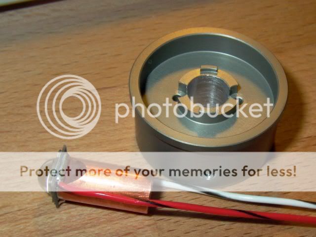
For the heatsink I used an idea I got from a LED Zeppelin post. It's an H22A heatsink for the P7. It's short enough to leave room for the driver. The DHS is hollow in the back was the reason for using a P7 heatsink instead. A piece of 3/8" copper bar forms the core of the heatsink. Since copper's thermal conductivity is twice that of aluminum, the heat goes through the core of the heatsink and then sideways. Instead of just radiating from the front of a solid aluminum heatsink. The copper bar was first faced off on a lathe. A file would do almost as well. Next it was clamped in a vise between cardboard at a 20° angle (no milling machine) and filed from both sides to make the mounting pad exactly 5.1 mm wide. The taper allows room to solder the wires afterwards. I drilled a 3/8" hole in the P7 heatsink on a drill press because I didn't have a boring tool that small or the correct size reamer. A Brown & Sharpe BestTest dial indicator chucked in the drill press got me on center. The hole being drilled was of course a little too big. During assembly I applied some MX-2 to a strip of aluminum foil 2.25" long. It gave me just shy of two wraps and was a nice tight fit in the heatsink. In fact it took 3 attempts because it ripped twice. I used MX-2 instead of Artic Silver 5 because AS5 is too thick to get a layer thin enough to avoid tearing the foil while creating a gap filler that is mostly metal. A 6-32 set screw holds the copper insert in place. The front of the LED board was mounted flush with the front of the heatsink in a test that put the rear of the reflector housing ≈ 2 mm from the potentiometer knob. The reflector focuses OK and still goes past. I think the shorter H22A heatsinks are the optimal size because they only extend as far into the battery tube as the reflector housing threads. Longer than that would only store the heat and not help dissipate it, IMO.
Some DX solder paste on the copper bar, sitting on an empty tomato paste can and using a stick lighter, took a minute or two to reflow the LED. I put a small streak of paste on the side of the copper thinking I would see it change color as a means of knowing when the solder melted. It turned out to be unnecessary as the vibration from turning the can on my textured Formica kitchen counter caused the LED to wiggle on the copper as the solder melted. Rather like watching high speed Jell-O shake. It was a very interesting and distinct sight. I put some water from an eyedropper at the base afterwards to cool it. There were some comments on the DX forum about this not being a "No-Clean" type of solder paste. Some alcohol and a small toothbrush took care of it with no problem.
The P7 heatsink was slightly too large to fit in the battery tube. I think it's possible that the new Mag tubes are slightly smaller than they used to be. Mine had an I.D. of 34.19 mm. That's a little bit small compared to other Mag-D's I've had and measurements I've seen others mention. The H22A heatsink was 34.26 mm O.D. and required ≈ 20 seconds fine sanding with a homemade jig in a hand drill to make it a perfect fit. It's ever so slightly snug and by the end gets tight. I'd rather it be too large initially than too small. Some AS5 compound "glues" it in place when finished.
One thing I had trouble with and would do differently is attaching the wires to the LED after being reflowed onto the 3/8" copper bar. I would attach the wires at the same time as the LED if I had it to do over. I used a two stage Weller soldering gun for the wire attachment. One of the big 150/75 watt ones that actually looks like a pistol. I thought the 75 watt setting would be enough but I had to crank it up to 150 watts for about 10 seconds for the solder on the wire to start flowing to the LED board. I wasn't really timing it. I realized the vias connections on the back of the LED for plus and minus do more than just supply power when reflowed onto an MCPCB. It might have had something to do with the °C/W rating of the SST-90 being 0.64 as opposed to 2.45 for the SST-50 that LED Zeppelin used. I never actually asked him if he had trouble attaching the wires. For a piece of ceramic or whatever material it is to absorb that much heat is truly amazing. On the plus side I took it as an indication that the copper core idea will work better than an MCPCB star. People solder mounted stars all the time without a 150 watt gun and have no problem. All of this is a little embarrassing as I had no plans of mentioning the use of the 150 watt soldering gun. I just thought anyone going down this road needed to be aware of the pitfalls. The idea was a lot of heat for a short interval is better than using a soldering gun too small for too long. Before anyone asks, I used a normal 40 watt gun for the other electronics. After the LED cooled I put a CR123A across the leads and it still worked. I though I fried it for sure. These Luminus LED's really do take abuse well.
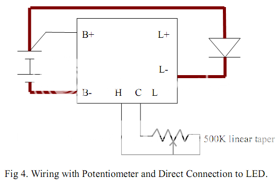
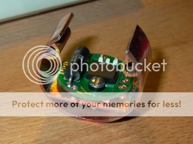
I used a DIWdiver IS1006-1025, 10 amp linear regulator. People's initial reaction to this board seemed to be that it's too much power for a linear regulator to handle. I have to say I'm very impressed with both the quality and performance of this board. Not to mention the fact it's the only full power board available so far. My 1,700 mAh 4/5-SubC Sanyo NiCad's fully charged and rested measure 5.47 volts. At full power to the LED I measure 4.96 volts on the batteries and 3.88 volts to the LED at 10.25 amps. That's an efficiency of 78% at full power, which is pretty good I think. It gets better as the batteries die just like a big AMC7135 would. I mounted the board sideways to allow room for a 500K potentiometer with a switch. A plus side of switching the B+ on the board instead of using a SPDT switch on the H-L-C connections is the off power drain drops to zero. A knurled knob allows for one handed operation by rolling your thumb on the side of the knob. DIWdiver had recommended a linear taper pot if not using the SPDT switch option. A log or audio taper pot makes the sensitivity problem at high power worse. I tried a linear taper pot (on my DMM) and found it to be too sensitive. Since anti-log pots are virtually unobtainium, I used a regular audio taper on the CCW side. That is it to say it comes on backwards at full power and gets dimmer as you turn it clockwise. I was OK with that. The high power sensitivity is perfect. The pot measured slightly over 500K but I don't remember exactly what. The power range on my particular board is 10.25 amps at full power and drops to 714 ma at low. The LED voltage at those settings are 3.88 and 2.94 volts respectively. That translates to 39.8 LED watts down to 2.1 watts, a pretty decent range I think. My battery life range is from slightly over 2 hours on low to about 8 minutes on high. That's allowing for a 20% heat reduction loss caused by the internal resistance of the battery. If you include the power dissipated by the regulator, it's over 50 watts total at full power. :devil:
Here is a diagram from DIWdiver's IS1006 draft2 showing the wiring I used.
A homemade heatsink from a $1.85 1" copper coupling took me about an hour or so to make. I got the idea from this post. I thought he came up with a very nice application of low cost material. I cut two pieces 5/8" wide from the coupling with a tubing cutter. One piece had a 90° segment cut from it with tin snips. The other piece was hammered flat and cut 1.125" long. The edges were beveled with a file to sit flat on the wall of the curved piece. The jaws of an old monkey wrench I have are about 3/4" wide. It was perfect for tightening on the wall of the sectored round piece as a means of changing its diameter to match the Mag battery tube. I held the flat piece it in place with a twist of picture hanging wire while I soldered it to the sector with a propane torch. The thick walled brass tubing was cut with a hacksaw close to the edge and filed flat. I stuffed some rolled up paper towel behind the flat shelf that had already been soldered. I wet it with an eyedropper to prevents the shelf joint from melting. I used an alligator clip to hold the 1/4" brass tubing in place while soldering because I couldn't find a paper clip. The tubing is soldered onto the ends of the loop for mounting or removing with needle nose pliers. They are not mounted on the very end for clearance of the potentiometer. The small tube "handles" really make insertion much easier. A small loop from a piece of Romex would work just as well. This is what I had lying around. My 270° copper sector could originally be squeezed a little less than 1/4" (at the gap) before permanently changing its diameter (spring tension limit). The shelf I soldered in place to mount the regulator on plus the insertion tubes cut that down to about 1/16". I used a TO-220 mounting kit to insulate the FET from the ground. I put MX-2 between the copper heatsink and the battery tube. A day later I could see it coming out the side a little from the pressure. Self leveling is something AS5 is just too thick to do.
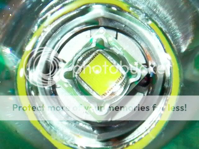
Here's a close-up showing where I beveled the edge of the LED with a carborundum stone. An LED measuring 10 mm * 11 mm, would theoretically have a 14.866 mm diagonal. Mine measure a little closer to 14.7 mm initially. The hole in the center of the reflector is 15.37 mm (on my sample). Considering how much wiggle there is in a Mag reflector housing, I felt a little uncomfortable with that and did not want to bore the reflector. Actually when it's all gooped up with AS3, the reflector housing barely turns let alone wiggles.
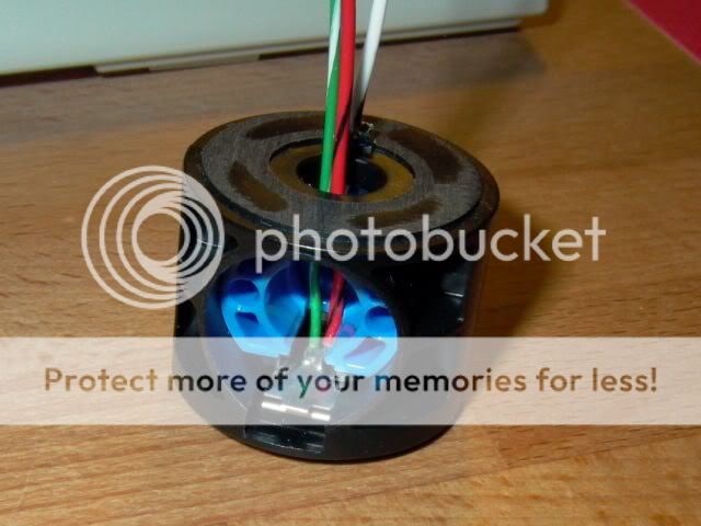
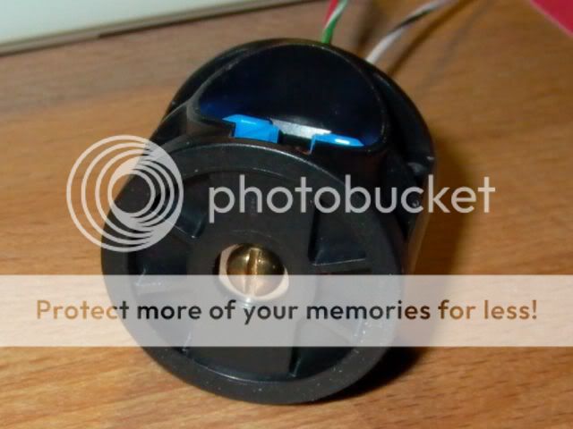
I like these new Mag switches. With the switch removed from the housing, the positive battery contact just slides out the side of the housing. The battery contact itself is chrome plated brass. I cut the head off a brass 8-32 screw and reflowed it onto the battery contact with my trusty stick lighter. I soldered a 20 gauge Teflon wire for the LED+ and a 24 gauge Teflon wire for the potentiometer switch that goes to the B+ connection on the regulator. What I liked was I could do the soldering outside the switch body without drilling holes or melting the switch. Then simply insert the battery contact back in the switch housing. Before putting the blue half of the switch back, I trimmed the small plastic tabs that normally hold the stock switch contacts in place. I didn't need the switch guts for my setup.
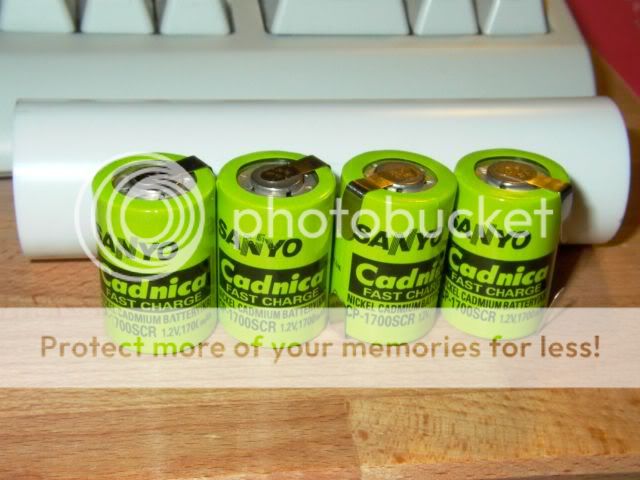
Here's a shot of the Sanyo NiCad's and a 5" piece of 1" schedule 40 PVC used as a spacer. Why use NiCad's instead of NiMH? These are 1,700 mAh and the Elite 4/5-SubC NiMH are only 2,200 mAh. It didn't seem like enough of a difference to make them worth while. I once "lost" a set of Cadnicas in a drawer for 10+ years. They took a charge with no problem. Try that with an NiMH cell. NiMH are also sensitive to impact. Not that I'm planning on dropping the light. I'd more likely do that while fumbling around with the batteries putting them in the charger. With an 8 minute run time I doubt I'll have to worry about memory effects. Back in the day when I was crashing RC planes, Sanyo NiCad's were the best available. Maybe it's just my nostalgia kicking in, but I think NiCad's can stand up to this kind of high drain abuse better. The real choice for me was not between NiCad and NiMH, but between 1,700 mAh 4/5-SubC's in a 2D-Mag and 5,000 mAh SubC's in a 3D-Mag. I just didn't want the extra length. I should have put a jack in the side of the light for charging, maybe later.
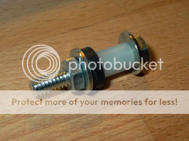
Here's a standard low resistance tailcap spring. The 4 Sanyo NiCad's are in total 12 mm longer than 2*D cells would be. I Dremeled off the extra loops on the top and bottom of the spring. It easily compresses flush with the tailcap now. Next to the spring is a keeper made from picture hanging wire. I used it to hold the brass washer in place while soldered it with a torch to the tailcap spring at about 20% compression. A folded over piece of solder braid was put onto a blob of solder on the end of the countersunk screw as it cooled. The edge of the screw is slightly sanded so it won't scratch the battery. It seemed so much neater than bending the spring with pliers to protect the battery's heat shrink tubing. Actually I did try bending the spring before soldering. I threw that one away. This is an old style spring I had lying around. The new springs have a dull chrome finish that chips off when you try to bend it. :sick2:
I was originally going to use a Deans Micro or Ultra connector to make the LED and heatsink removable if any repairs were needed later. I had both lying around. The Deans Micro is rated for use up to 10 amps (I called and asked). It turned out I didn't have any room for it though. I kept the heat shrink tubing short enough to just cover the splice. That way I can easily cut it off if need be without damaging the wires. If you look closely you can see where I ground down the end of the copper core with a cut-off wheel in the Dremel to prevent it from hitting the FET leads on the regulator. The heatsink mounting shelf could have easily been made shorter to mount lower, if I had measured it correctly in the first place.:whoopin: It didn't cause any serious problem though.
Here are a few comparative beamshots @ 11'9" or 3.58 meters. My TV's entertainment center is on the opposite wall with the lights resting on it. The picture on the wall is 20" wide and 62" from the edge of the wall to give it some scale. The SST-90 WM-F3 2D-Mag is on the left and a 3D-Mag CSXPI P7 using 10 Ah NiMH D's is on the right. Both lights have stock plastic reflectors with the cam tube cut off. The hot spot of the SST-90 is only slightly larger than a P7's. But it has more of its light spread out in the corona. Something you would expect given the comatic aberration a high speed parabolic reflector creates imaging such a large target. What surprised me was the hot spots are almost the same size. Something I wasn't expecting given the SST-90 is ≈ 50% larger than an SSC P7. There is absolutely no trace of a donut.") It's definitely brighter, but it doesn't look 3 times brighter. I don't own a lux meter or an integrating sphere, so I can't really tell. I should have gone for the 'N' bin.
It's definitely brighter, but it doesn't look 3 times brighter. I don't own a lux meter or an integrating sphere, so I can't really tell. I should have gone for the 'N' bin.
1/250 second @ f/8

1/250 second @ f/4

1/250 second @ f/2.4

The P7 was at least a fair fight, but this one I have to laugh at. On the left is the SST-90 Mag @ 714 ma, in the middle an Olight T20-Q5 on high and on the right a Fenix P3D-Q5 in Turbo mode. The P3D was never 100% in focus so it might look dimmer than the Olight, but it really isn't. They are all about the same level of intensity. The color of the SST-90 does shift slightly at low power with this type of regulator. But it's not objectionable.
1/250 second @ f/2.4

Here we go at 10.25 amps. If you look closely you can see the others are still on. They just can't compete with 40 watts.
1/250 second @ f/8

If anybody has any questions, please feel free to ask away.
Thanks for looking :wave:
I started with an SST-90 WM-F3 from 4Sevens. He ran out of that bin fairly quick being such a nice color. I figured I could live with it being an M bin since it was only 28 bucks. According to the Luminus specs, it's still over 2,000 lumens at full power. A Fivemega Finned/Flutted M*g "D" Head is just the ticket to dissipate all that heat. Sorry folks, I got the last one for now. I used some Arctic Silver 3 to mount fivemega's reflector housing to the battery tube. I figure that to be the perfect way to enhance this modified housing's heat dissipating abilities. Nyogel 760 was used only on the O-ring. In case anyone is wondering, I bought a huge tube of AS3 about a month before they came out with AS5. AS3 is much thinner than AS5 and so better suited to this. I always knew I'd find a use for it. The combination of extra surface area of the finned head and AS3 really seemed to do the trick. I had it running for about 2 minutes at full power just to see. It was hot, but not so hot I couldn't touch it. [Edit: I forgot to mention the use of a flashlightlens.com UCL cover glass. Don't know how I forgot that]
For the heatsink I used an idea I got from a LED Zeppelin post. It's an H22A heatsink for the P7. It's short enough to leave room for the driver. The DHS is hollow in the back was the reason for using a P7 heatsink instead. A piece of 3/8" copper bar forms the core of the heatsink. Since copper's thermal conductivity is twice that of aluminum, the heat goes through the core of the heatsink and then sideways. Instead of just radiating from the front of a solid aluminum heatsink. The copper bar was first faced off on a lathe. A file would do almost as well. Next it was clamped in a vise between cardboard at a 20° angle (no milling machine) and filed from both sides to make the mounting pad exactly 5.1 mm wide. The taper allows room to solder the wires afterwards. I drilled a 3/8" hole in the P7 heatsink on a drill press because I didn't have a boring tool that small or the correct size reamer. A Brown & Sharpe BestTest dial indicator chucked in the drill press got me on center. The hole being drilled was of course a little too big. During assembly I applied some MX-2 to a strip of aluminum foil 2.25" long. It gave me just shy of two wraps and was a nice tight fit in the heatsink. In fact it took 3 attempts because it ripped twice. I used MX-2 instead of Artic Silver 5 because AS5 is too thick to get a layer thin enough to avoid tearing the foil while creating a gap filler that is mostly metal. A 6-32 set screw holds the copper insert in place. The front of the LED board was mounted flush with the front of the heatsink in a test that put the rear of the reflector housing ≈ 2 mm from the potentiometer knob. The reflector focuses OK and still goes past. I think the shorter H22A heatsinks are the optimal size because they only extend as far into the battery tube as the reflector housing threads. Longer than that would only store the heat and not help dissipate it, IMO.
Some DX solder paste on the copper bar, sitting on an empty tomato paste can and using a stick lighter, took a minute or two to reflow the LED. I put a small streak of paste on the side of the copper thinking I would see it change color as a means of knowing when the solder melted. It turned out to be unnecessary as the vibration from turning the can on my textured Formica kitchen counter caused the LED to wiggle on the copper as the solder melted. Rather like watching high speed Jell-O shake. It was a very interesting and distinct sight. I put some water from an eyedropper at the base afterwards to cool it. There were some comments on the DX forum about this not being a "No-Clean" type of solder paste. Some alcohol and a small toothbrush took care of it with no problem.
The P7 heatsink was slightly too large to fit in the battery tube. I think it's possible that the new Mag tubes are slightly smaller than they used to be. Mine had an I.D. of 34.19 mm. That's a little bit small compared to other Mag-D's I've had and measurements I've seen others mention. The H22A heatsink was 34.26 mm O.D. and required ≈ 20 seconds fine sanding with a homemade jig in a hand drill to make it a perfect fit. It's ever so slightly snug and by the end gets tight. I'd rather it be too large initially than too small. Some AS5 compound "glues" it in place when finished.
One thing I had trouble with and would do differently is attaching the wires to the LED after being reflowed onto the 3/8" copper bar. I would attach the wires at the same time as the LED if I had it to do over. I used a two stage Weller soldering gun for the wire attachment. One of the big 150/75 watt ones that actually looks like a pistol. I thought the 75 watt setting would be enough but I had to crank it up to 150 watts for about 10 seconds for the solder on the wire to start flowing to the LED board. I wasn't really timing it. I realized the vias connections on the back of the LED for plus and minus do more than just supply power when reflowed onto an MCPCB. It might have had something to do with the °C/W rating of the SST-90 being 0.64 as opposed to 2.45 for the SST-50 that LED Zeppelin used. I never actually asked him if he had trouble attaching the wires. For a piece of ceramic or whatever material it is to absorb that much heat is truly amazing. On the plus side I took it as an indication that the copper core idea will work better than an MCPCB star. People solder mounted stars all the time without a 150 watt gun and have no problem. All of this is a little embarrassing as I had no plans of mentioning the use of the 150 watt soldering gun. I just thought anyone going down this road needed to be aware of the pitfalls. The idea was a lot of heat for a short interval is better than using a soldering gun too small for too long. Before anyone asks, I used a normal 40 watt gun for the other electronics. After the LED cooled I put a CR123A across the leads and it still worked. I though I fried it for sure. These Luminus LED's really do take abuse well.
I used a DIWdiver IS1006-1025, 10 amp linear regulator. People's initial reaction to this board seemed to be that it's too much power for a linear regulator to handle. I have to say I'm very impressed with both the quality and performance of this board. Not to mention the fact it's the only full power board available so far. My 1,700 mAh 4/5-SubC Sanyo NiCad's fully charged and rested measure 5.47 volts. At full power to the LED I measure 4.96 volts on the batteries and 3.88 volts to the LED at 10.25 amps. That's an efficiency of 78% at full power, which is pretty good I think. It gets better as the batteries die just like a big AMC7135 would. I mounted the board sideways to allow room for a 500K potentiometer with a switch. A plus side of switching the B+ on the board instead of using a SPDT switch on the H-L-C connections is the off power drain drops to zero. A knurled knob allows for one handed operation by rolling your thumb on the side of the knob. DIWdiver had recommended a linear taper pot if not using the SPDT switch option. A log or audio taper pot makes the sensitivity problem at high power worse. I tried a linear taper pot (on my DMM) and found it to be too sensitive. Since anti-log pots are virtually unobtainium, I used a regular audio taper on the CCW side. That is it to say it comes on backwards at full power and gets dimmer as you turn it clockwise. I was OK with that. The high power sensitivity is perfect. The pot measured slightly over 500K but I don't remember exactly what. The power range on my particular board is 10.25 amps at full power and drops to 714 ma at low. The LED voltage at those settings are 3.88 and 2.94 volts respectively. That translates to 39.8 LED watts down to 2.1 watts, a pretty decent range I think. My battery life range is from slightly over 2 hours on low to about 8 minutes on high. That's allowing for a 20% heat reduction loss caused by the internal resistance of the battery. If you include the power dissipated by the regulator, it's over 50 watts total at full power. :devil:
Here is a diagram from DIWdiver's IS1006 draft2 showing the wiring I used.
A homemade heatsink from a $1.85 1" copper coupling took me about an hour or so to make. I got the idea from this post. I thought he came up with a very nice application of low cost material. I cut two pieces 5/8" wide from the coupling with a tubing cutter. One piece had a 90° segment cut from it with tin snips. The other piece was hammered flat and cut 1.125" long. The edges were beveled with a file to sit flat on the wall of the curved piece. The jaws of an old monkey wrench I have are about 3/4" wide. It was perfect for tightening on the wall of the sectored round piece as a means of changing its diameter to match the Mag battery tube. I held the flat piece it in place with a twist of picture hanging wire while I soldered it to the sector with a propane torch. The thick walled brass tubing was cut with a hacksaw close to the edge and filed flat. I stuffed some rolled up paper towel behind the flat shelf that had already been soldered. I wet it with an eyedropper to prevents the shelf joint from melting. I used an alligator clip to hold the 1/4" brass tubing in place while soldering because I couldn't find a paper clip. The tubing is soldered onto the ends of the loop for mounting or removing with needle nose pliers. They are not mounted on the very end for clearance of the potentiometer. The small tube "handles" really make insertion much easier. A small loop from a piece of Romex would work just as well. This is what I had lying around. My 270° copper sector could originally be squeezed a little less than 1/4" (at the gap) before permanently changing its diameter (spring tension limit). The shelf I soldered in place to mount the regulator on plus the insertion tubes cut that down to about 1/16". I used a TO-220 mounting kit to insulate the FET from the ground. I put MX-2 between the copper heatsink and the battery tube. A day later I could see it coming out the side a little from the pressure. Self leveling is something AS5 is just too thick to do.
Here's a close-up showing where I beveled the edge of the LED with a carborundum stone. An LED measuring 10 mm * 11 mm, would theoretically have a 14.866 mm diagonal. Mine measure a little closer to 14.7 mm initially. The hole in the center of the reflector is 15.37 mm (on my sample). Considering how much wiggle there is in a Mag reflector housing, I felt a little uncomfortable with that and did not want to bore the reflector. Actually when it's all gooped up with AS3, the reflector housing barely turns let alone wiggles.
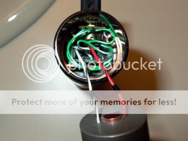
I like these new Mag switches. With the switch removed from the housing, the positive battery contact just slides out the side of the housing. The battery contact itself is chrome plated brass. I cut the head off a brass 8-32 screw and reflowed it onto the battery contact with my trusty stick lighter. I soldered a 20 gauge Teflon wire for the LED+ and a 24 gauge Teflon wire for the potentiometer switch that goes to the B+ connection on the regulator. What I liked was I could do the soldering outside the switch body without drilling holes or melting the switch. Then simply insert the battery contact back in the switch housing. Before putting the blue half of the switch back, I trimmed the small plastic tabs that normally hold the stock switch contacts in place. I didn't need the switch guts for my setup.
Here's a shot of the Sanyo NiCad's and a 5" piece of 1" schedule 40 PVC used as a spacer. Why use NiCad's instead of NiMH? These are 1,700 mAh and the Elite 4/5-SubC NiMH are only 2,200 mAh. It didn't seem like enough of a difference to make them worth while. I once "lost" a set of Cadnicas in a drawer for 10+ years. They took a charge with no problem. Try that with an NiMH cell. NiMH are also sensitive to impact. Not that I'm planning on dropping the light. I'd more likely do that while fumbling around with the batteries putting them in the charger. With an 8 minute run time I doubt I'll have to worry about memory effects. Back in the day when I was crashing RC planes, Sanyo NiCad's were the best available. Maybe it's just my nostalgia kicking in, but I think NiCad's can stand up to this kind of high drain abuse better. The real choice for me was not between NiCad and NiMH, but between 1,700 mAh 4/5-SubC's in a 2D-Mag and 5,000 mAh SubC's in a 3D-Mag. I just didn't want the extra length. I should have put a jack in the side of the light for charging, maybe later.
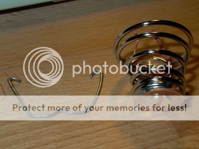
Here's a standard low resistance tailcap spring. The 4 Sanyo NiCad's are in total 12 mm longer than 2*D cells would be. I Dremeled off the extra loops on the top and bottom of the spring. It easily compresses flush with the tailcap now. Next to the spring is a keeper made from picture hanging wire. I used it to hold the brass washer in place while soldered it with a torch to the tailcap spring at about 20% compression. A folded over piece of solder braid was put onto a blob of solder on the end of the countersunk screw as it cooled. The edge of the screw is slightly sanded so it won't scratch the battery. It seemed so much neater than bending the spring with pliers to protect the battery's heat shrink tubing. Actually I did try bending the spring before soldering. I threw that one away. This is an old style spring I had lying around. The new springs have a dull chrome finish that chips off when you try to bend it. :sick2:
I was originally going to use a Deans Micro or Ultra connector to make the LED and heatsink removable if any repairs were needed later. I had both lying around. The Deans Micro is rated for use up to 10 amps (I called and asked). It turned out I didn't have any room for it though. I kept the heat shrink tubing short enough to just cover the splice. That way I can easily cut it off if need be without damaging the wires. If you look closely you can see where I ground down the end of the copper core with a cut-off wheel in the Dremel to prevent it from hitting the FET leads on the regulator. The heatsink mounting shelf could have easily been made shorter to mount lower, if I had measured it correctly in the first place.:whoopin: It didn't cause any serious problem though.
Here are a few comparative beamshots @ 11'9" or 3.58 meters. My TV's entertainment center is on the opposite wall with the lights resting on it. The picture on the wall is 20" wide and 62" from the edge of the wall to give it some scale. The SST-90 WM-F3 2D-Mag is on the left and a 3D-Mag CSXPI P7 using 10 Ah NiMH D's is on the right. Both lights have stock plastic reflectors with the cam tube cut off. The hot spot of the SST-90 is only slightly larger than a P7's. But it has more of its light spread out in the corona. Something you would expect given the comatic aberration a high speed parabolic reflector creates imaging such a large target. What surprised me was the hot spots are almost the same size. Something I wasn't expecting given the SST-90 is ≈ 50% larger than an SSC P7. There is absolutely no trace of a donut.
It's definitely brighter, but it doesn't look 3 times brighter. I don't own a lux meter or an integrating sphere, so I can't really tell. I should have gone for the 'N' bin.1/250 second @ f/8
1/250 second @ f/4
1/250 second @ f/2.4
The P7 was at least a fair fight, but this one I have to laugh at. On the left is the SST-90 Mag @ 714 ma, in the middle an Olight T20-Q5 on high and on the right a Fenix P3D-Q5 in Turbo mode. The P3D was never 100% in focus so it might look dimmer than the Olight, but it really isn't. They are all about the same level of intensity. The color of the SST-90 does shift slightly at low power with this type of regulator. But it's not objectionable.
1/250 second @ f/2.4
Here we go at 10.25 amps. If you look closely you can see the others are still on. They just can't compete with 40 watts.
1/250 second @ f/8
If anybody has any questions, please feel free to ask away.
Thanks for looking :wave:
Last edited:
 Really the thing I like best about this light so far is going from P3D to HID with the twist of a knob.