Need help designing custom copper MCPCB for an XML

archer6817j

Enlightened
Joined
Aug 9, 2010
Messages
830
Location
Mountain View, CA
Hi folks,

I've been talking to some MCPCB manufacturers about making custom 2mm thick copper core boards to use in my custom lights.

I just saw the "thermal path" thread and realized I should ask the experts here to get some advice and to make sure I'm getting my money's worth from the manufacturer.

First of all, my application has some limitations and I won't be able to create the "ideal" thermal situation but I want to make it as good as possible with what I've got to work with.

I've also been updating my testing methods to the ANSI standard for output. The good news is that @ 3 mintues the output is stable. The bad news is, I'm loosing about 100 lumens compared to the "@ turn on" output. I'd like to get this loss down as much as possible. Here are the constraints:

1) I'm using a solid head (no pill) and the LED is inserted from the front of the head. The surface immediately behind where the LED is mounted is 3/8" of aluminum...but keep in mind the head is solid.

head+section.jpg


2) I'm using thermal tape with no screws, but following the manufacturer's recommendation for pressure and time. I know this isn't as good as arctic silver and screws but the main reason I'm doing this is that the screws interfere with the optics I'm using (and most optics I've tried). So, I decided the best way to increase the thermal efficiency is to go with a copper MCPCB vs. an aluminum one.
3) the MCPCB thickness will be 2mm. This is the thickness of my current aluminum MCPCBs and I can't go any thicker without altering the dimensions of the head. However, it seems like 2mm should be a "decent" thickness considering the copper stars from KD (or wherever) are around .8mm
4) the star size is 20mm

So, given the above, do you have any thoughts or advice on the physical design of the board with respect to trace layout, circuit layer thickness, dielectric layer thickness, etc?

Is this something people would be interested in purchasing as a component? The cost is quite high at a volume of 100 pcs...say in the neighborhood of $15 just for the MCPCB (not including the LED).

Let the games begin!
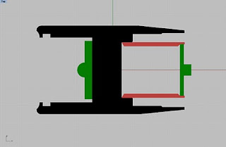
 

CKOD

Enlightened
Joined
Aug 3, 2010
Messages
708
for 2), Use arctic silver thermal adhesive or arctic alumina thermal adhesive if possible, this makes rework at a later point difficult. Heat should degrade the epoxy, so you may be able to bake the head/MCPCB, degrade the epoxy and use a screwdriver or the like to sheer the PCB from the base. But I'd call that a permanent solution either way. If you want to be able to change it out, find the best tape you can.

For your MCPCB, you want to use the best electrical insulation/thermally conductive layer you can get, I dont know any by name, others may, but this is the bottleneck, and where MCPCBs go good or bad. As far as layout, get the heaviest copper you can get for the top copper, IIRC 8oz + copper is available, no 1 oz sissy stuff here, kthx ;) And you want to flood as much of the board as possible to allow for as much radial heat spreading you can get before it has to go though the insulator layer. You dont need the thermal pad to be isolated from both electrical pads on a single LED, so the only one lead needs to be isolated from the rest of the copper flood on top, and just use soldermask to define the pads. For the solder pads for soldering your wire, try and add some thermal relief, MCPCBs are hard enough to solder too.
http://en.wikipedia.org/wiki/File:PCB_copper_pour_thermal_pads.png
similar to how all the pads that are connected to the pour in that image are.


If youre trying to sell the stars, obviously screw slots will be needed for other people, if not, then just go with whatever fits your application.

edit:
scratch all that about the flood/insulator etc...

http://www.metalcorepcb.com/en/pcb-capabilities/mcpcb/design-construction/stack-up-drawing-for-mcpcb

if you get PCBs made with a direct thermal connection to the substrate, like in picture 7 on the link above
( http://www.metalcorepcb.com/images/Stack%20Up%20Drawing%206.png ) I know you could sell some MCPCBs on here. Thats what all the junkies that love to drive the heck out of LEDs want. If they turned out to be in the $15/per range, and they were the usual star shape for screwholes, I might consider buying ~36-40 or so. Obviously lower is better.
 
Last edited:

bshanahan14rulz

Flashlight Enthusiast
Joined
Jan 29, 2009
Messages
2,819
Location
Tennessee
Never used arctic silver epoxy, but couldn't you use the epoxy and screws, but just remove the screws after the epoxy has had time to set? If that's the only reason you are avoiding

Directly attaching the heat pad on the LED to the metal material of the MCPCB would be best, but if that isn't possible, try to spread the trace that attaches to the heat pad on the LED to the largest area you can, while still allowing enough room for sufficient traces for the anode and cathode traces.

You probably already figured these things, but it might as well be said for whoever digs up this thread in the future.
 

srfreddy

Enlightened
Joined
Sep 21, 2010
Messages
921
Location
New England
Thermal tape is really poor for conduction...couldn't you just clamp the star down and epoxy it? Or even just use the reflector to push the star down....
 

onetrickpony

Enlightened
Joined
Mar 10, 2011
Messages
262
Here's a thought: Counter sink the screws! Have the stars machined with counter-sunk holes, or just have holes and counter sink them yourself, then just use some thermal compound (paste) and screw the suckers down. Best of all possible solutions, and it won't interfere with your optic.

Metal to metal contact with just enough thermal gunk to fill in the voids seems to be the accepted ideal method of heat transfer in most situations. Just make sure you use a counter sink that matches screws you have available.
 

MikeAusC

Enlightened
Joined
Jul 8, 2010
Messages
995
Location
Sydney, Australia
If you're going to the effort of making a super-conductive star, it seems such a waste to then put in a thermal-tape heat barrier in front of the torch body.

The best thermal compound has conductivity at least ten times worse than aluminium - it should only be used to fill in the air gaps resulting from irregularities in two smooth metal surfaces.
 

onetrickpony

Enlightened
Joined
Mar 10, 2011
Messages
262
If you're going to the effort of making a super-conductive star, it seems such a waste to then put in a thermal-tape heat barrier in front of the torch body.

The best thermal compound has conductivity at least ten times worse than aluminium - it should only be used to fill in the air gaps resulting from irregularities in two smooth metal surfaces.

Eggggsactly.
 

archer6817j

Enlightened
Joined
Aug 9, 2010
Messages
830
Location
Mountain View, CA
I agree that thermal tape may not be the "ideal" solution. However, could you agree that a copper MCPCB would be at least incrementally better than using an aluminum one? Without actual data I find it hard to say to what extent one solution is better than another. I think "heat barrier" might be a little over the top when describing thermal tape :)

My hope: by using a copper MCPCB w/ thermal tape I can get thermal performance that is at least on par with an aluminum MCPCB and screwed down with AS. My understanding is that moving head away from the LED heat pad is the primary objective. I wish I could see a temperature gradient map with both the alu and copper MCPCBs. My hunch is that the copper moves the heat away so quickly that the ability to dissipate the heat into the flashlight head is less important than if you had an aluminum MCPCB. I'll keep thinking about a better "screw down" solution. I find it confusing that MANY optics and holders cannot accommodate screw heads or even stars with wires soldered to them...or perhaps that people that design stars don't think about attaching optics!

In the end I suppose I'm chasing incremental improvement, not the end-all solution for LED cooling :) If I can figure out how to get some sample copper boards it would be great to do some applied science and actually measure relative outputs in my sphere, with different MCPCB and thermal compound configurations. I supposes given the crowd here that might have been done already. Anyone know?
 

Oznog

Enlightened
Joined
Dec 2, 2006
Messages
595
I agree that thermal tape may not be the "ideal" solution. However, could you agree that a copper MCPCB would be at least incrementally better than using an aluminum one? Without actual data I find it hard to say to what extent one solution is better than another. I think "heat barrier" might be a little over the top when describing thermal tape :)
I would say no, actually.

First off, modern MCPCBs are QUITE good. The C/W of the package and heatsink are probably much more significant than the MCPCB.

Second, I'm pretty sure almost, well, NONE of the thermal resistance comes from the aluminum MCPCB body itself. It's in the electrical isolator, with a thermal resistance orders of magnitude greater than the aluminum, but nonetheless, not very significant in the big picture. It IS important that the top copper be over as much area as possible and is as thick as practical to minimize the lateral thermal resistance. See, if there's not lateral spread on top and the heat path is only of the area of the slug, the thermal resistance IS high. If the heat spreads out 1cm laterally from the slug and transfers heat through a wider area of the insulator, it's much lower.

Aluminum XML MCPCBs should be under 2C/W to begin with. Copper will only be SLIGHTLY less, because the insulator is still there.

DX sells or used to sell a copper-MCPCB XML for a few bucks more than the regular. That's your shortcut right there. I don't have the SKU though.
 

Nos

Enlightened
Joined
Dec 21, 2007
Messages
461
Location
Germany
DX sells or used to sell a copper-MCPCB XML for a few bucks more than the regular. That's your shortcut right there. I don't have the SKU though.

ma sha1 did some testing with those DX copper stars, but both tests failed afer soldering (see post#59), probably due to bad leads on in the star :(

I still think a star without a insulator under the termal pad of the emitter would a great idea. And of course this star has to be made of copper since its hard to solder on aluminium.
 

srfreddy

Enlightened
Joined
Sep 21, 2010
Messages
921
Location
New England
I think that the thermal tape should not be there-your star doesn't do anything if the heat is transfering very slowly to the heatsink.
 

SemiMan

Banned
Joined
Jan 13, 2005
Messages
3,899
I got a bit "lambasted" on another thread for suggesting that proper calculations are needed, but in this case, that is exactly what is needed.

1) Are you using a recognized metal core board supplier, or just buying from DX or similar where you can't get proper specifications? If you are using a proper metal core board supplier, what is the thermal resistance (or conductivity) of the insulator and how thick is the surface copper? At first pass I expect that you have a so-so board but would like to be wrong.

2) How thick is the metal core board?

3) What are the characteristics of the thermal tape you are using in terms of thermal resistance/conductance?

Once you have these parameters you can approximate your thermal resistance at each point and determine where the biggest gains are and by how much. If I had to hazard a guess on the limited information:

a) Heat sink is too small. If you are losing 100 lumens and it is stabilizing after 3 minutes then odds are your heat sink is probably on the small size.
b) Poor metal core board in that the thermal interface material is no good and copper on surface is too thin and/or poor contact between the LED and board. Could be wrong here, but have seen it often enough to expect it.
c) Thermal tape: Thermal tape is not great, but on the other hand you have a lot more surface area so even though resistance/area is higher, there is a lot of area to transfer heat.

My expectation is that copper over aluminum is going to solve little until you solve the basics first. Of course your copper board should be quite good.

You said you lost 100 lumens, but where did you start. If you started with 1000, then losing 100 is bad, but again, you have a small heatsink so perhaps your expectations are high. How hot does the heat sink get?

Your bare board costs are so high because your volume is low. Setup charges on metal core boards are high so you end up paying a lot of money unless you run volumes of material.

Semiman
 

archer6817j

Enlightened
Joined
Aug 9, 2010
Messages
830
Location
Mountain View, CA
Anyone here use solidworks/cosmos? I have a full seat but don't really know how to use cosmos. I imagine they have some sort of thermal simulation tool?

Semiman:

1) I buy my leds pre-mounted from cutter. I don't have any specs for those boards
2) The MCE board is 2mm thick and the XML board is 1.6mm
3) Thermal tape is Bond-Ply 100 (5mil) http://www.bergquistcompany.com/thermal_materials/bond_ply/bond-ply-100_5.htm

The entire head of the light is the heat sink, so making the heat sink bigger means a bigger light. The head gets quite hot if you let it run in air. I think part of the limitation is putting a lot of power into a 1" light. This is basically pushing the envelope and I'm trying to get more power and better lumen maintenance without increasing the size...and no, I'm not going to start making solid copper heads...unless anyone wants to buy them? I also want to keep in mind the thermal sag is only an issue if you are running full throttle.

As for the lost lumens with the MCE:

Turn on: 575
30 sec: 553
3 min: 445

The XMLs strange results:

Turn on: 610
30 sec: 575
3 min: 453

So, the XML starts out (a bit) brighter but settles to exactly the same point. Keep in mind the XML is on a 1.6mm star and the MCE is on a 2mm star.

I have been looking at some of the lists of lumen readings from Bigchelis (he helped me calibrate my own sphere) and it seems like I'm in the top 1/3 for performance on 2.8A regulated single-MCE lights. There are many that are a lot lower. Obviously this doesn't compete with direct drive. However, I was surprised that many production lights have as much (if not more) drop in lumen output than my lights. From that I infer that I'm doing "something" right but I'd like to move closer to the top of that list :)

I'm off to the shop to do some science!
 

archer6817j

Enlightened
Joined
Aug 9, 2010
Messages
830
Location
Mountain View, CA
I think that the thermal tape should not be there-your star doesn't do anything if the heat is transfering very slowly to the heatsink.

Hey srfreddy,

That's true but I don't know that the heat is transferring "very slowly." Since there is no data available there is no way to quantify "very." I will concede that it's transferring "more slowly" than if I used AS-5. However, we still don't know what the target rate of heat transfer is. Of course more heat transfer is better, but at some point there is a diminishing return. For example if the LED is a luxeon rebel driven at 750ma...using indium to solder it to a pound of copper probably isn't going to get a lot more output than if it was just soldered to a low quality aluminum star. So, if AS-5 and screws can get me 50 more lumens, I'm on board. If the difference is 10 lumens...then the hassle of drilling, tapping, coutnersinking, dropping tiny screws on the floor, applying AS, getting it all over, etc...isn't worth it. :)

Same goes for the copper boards, if it's 50 lumens it's worth the expense. If it's less...diminishing return. It's all relative, for me at lest. Does that mean you aren't going to buy a light till I get rid of that thermal tape? :)
 

MikeAusC

Enlightened
Joined
Jul 8, 2010
Messages
995
Location
Sydney, Australia
The majority opinion here seems to be against using Thermal tape because there are much easier ways of dramatically reducing the temperature drop.

All other options involve metal to metal contact - except for the air pockets cause by surface irregularities.

Thermal tape totally prevents ANY metal-to-metal contact.

No-one here has quoted practical measurements of temperature drop across Thermal Tape - because no-one here uses it.

When people complain about poor thermal performance using grease or epoxy, it's when they don't understand the significance or metal-to-metal contact and they don't apply pressure to ensure that compound only fills in surface irregularities - not using compounds as a barrier layer.
 

Oznog

Enlightened
Joined
Dec 2, 2006
Messages
595
You don't need Cosmos flow to calculate heat here.

A 20mm star is about 0.5sq in. The thermal tape would be 1.12C/W IF high pressure (>10PSI) is used to seat it. You should be using thermal epoxy (Arctic Silver).

A Star is "under" 2C/W total, insulator and metal. Thermal resistance if junction-to-pad inside the XML itself is 2.5C/W.

Aluminum is 250 k-W/(m*K). So a 20mm Star is about 0.00034 m^2 and about 0.00175m thick. If I calc'ed that right, I get 0.0206 C/W in the aluminum itself.
Which means the thermal resistance of the aluminum is already so close to zero, copper won't improve anything. ALL the thermal resistance is coming from the insulator layer and the aluminum clearly doesn't matter at all.

Well, the calc is flawed because the Star's utilization of the aluminum depends on how much area the top copper trace spreads it out over. But it's beside the point- if it were 10x higher than that, it STILL would hardly be significant!

If you're seeing high thermal resistance, it's probably coming from the thermal tape. No serious LED modder will use that, it's too high for these small areas, and if you have no screws, it probably won't work reliably. That's your problem. Like I say, Arctic Silver.

Heat's always an issue, but a lot of people obsess over it far beyond its true significance. The XML loses 10% of its output if the die temp increases 50C. So, OK, if you're running REALLY intense at 10W, the thermal board's 2C/W is causing a temp rise responsible for a 4% share of degradation of output. That's... not much. Sure, it'll also degrade a bit faster due to the extra 20C die temp, although in a flashlight it'll probably become obsolete before the die degrades. In any case, the heatsink is probably gonna be >2C/W so the Star is hardly the problematic factor.
 
Last edited:

Al Combs

Enlightened
Joined
Jul 2, 2007
Messages
872
I agree that thermal tape may not be the "ideal" solution. However, could you agree that a copper MCPCB would be at least incrementally better than using an aluminum one?

I think you are on the right track with the copper star idea. I believe it represents more than just an incremental improvement. The other thread I pointed to Mick made the case of 20+ watts of an SST-90 (really more like 35 watts) going through a thermal vias that only has a surface area of 5.1mm x 9mm. The XM-L's thermal pad is only 2.8mm x 4.8mm. The surface area of the XM-L thermal pad vs the amount of heat it has to dissipate is in similar ratio to that of the SST-90.

I have two links from Lux-RC here and here. He's the guy that makes the 20mm triple XP-G R5 stars. The first shows a picture of raised contact pads on his new style gold plated copper stars. Look towards the bottom of the page for a thumbnail link to a larger picture. Later the insulating layer and the traces for electrical contact are added making the overall surface flush. When he re-flows an LED, it's being solder directly to gold plated copper. The second is a discussion thread where he mentions copper has ≈ 100 times the thermal conductivity of the best insulating materials available on common stars.

As a quantitative example of that concept, on page 13 of the Luminus SST-90-W data sheet, the thermal resistance from the junction to the ceramic substrate is 0.64°C/W. Once it's mounted on an MCPCB star, the thermal resistance increases to 2.02°C/W. It's not that aluminum is a crappy material to make stars from. It's the insulator used under the contact pads that becomes the limiting factor. At the 35 watt power level, the SST-90 junction is 22.4°C hotter than the back surface of the ceramic substrate but 70.7°C warmer than the back of a MCPCB star! Another way of looking at that might be to say when the head of a flashlight with a star mounted LED is 29.3°C / 84.74°F or barely warm to the touch, the LED junction is already hot enough to boil water.

Referring again to page 13 of the SST-90 data sheet, the eGraf 1205 TIM Luminus used in their test only increased thermal resistance another 0.13°C/W. Thermal tape is fine as long as it has a large enough surface area to dissipate the heat through. Incidentally, I downloaded the pdf file on eGraf 1205 that Luminus mentioned just to see and that particular TIM has more than double the thermal conductivity of what Lux-RC refers to as, "thermally-enhanced insulator material". See the section labeled, "Improved Heat Conductivity". Thermal conductivity of the enhanced insulator on the MCPCB star is only 5.0 W/mK while the eGraf 1200 TIM is 12W/mK. The 1205 is the thinnest in the series @ 5 mills thick.

So here's a hopefully not too provocative question for the group. If using a TIM for thermal coupling is by consensus a bad idea, how can considering the use of an MCPCB star in the first place be a good one?;)
 
Last edited:

bshanahan14rulz

Flashlight Enthusiast
Joined
Jan 29, 2009
Messages
2,819
Location
Tennessee
MCPCBs are about compromise, and I think that is what the OP is going for, something that is easy to assemble but still performs better than the mass-produced silicone-the-star china lights.

BTW, that DS333 blank looks beautiful!
 

MikeAusC

Enlightened
Joined
Jul 8, 2010
Messages
995
Location
Sydney, Australia
. . . . So here's a hopefully not too provocative question for the group. If using a TIM for thermal coupling is by consensus a bad idea, how can considering the use of an MCPCB star in the first place be a good one?;)

The unchangeable problem isn't the star - it's the tiny surface area at the back of the chip that is such a small area to conduct the heat out of the LED - while also providing the electrical connection.

It doesn't matter whether you mount the LED+ceramic onto a block of copper or an aluminium star - all the heat has to spread from that small area.

That's why 99% of high-power LEDs are mounted on stars - it works almost as well as the next best thing. If you're trying to get the last possible Lumen out of the LED you do something else - but it's a lot more work for a little extra benefit.
 
Top