
DavidMB
Newly Enlightened
- Joined
- Jan 5, 2005
- Messages
- 112
Recently I bought the Sunwayman V10A. Right out of the box I found that the control ring was acting strange. When rotating from low to high it was smooth with just the right amount of resistance, then it seemed to slip and rotate without resistance towards the high end. Figured I would investigate this and found this link on how to take it apart.
http://www.candlepowerforums.com/vb/showthread.php?310269-Sunwayman-V10R-TI-Neutral-XP-G-Mod
I didn't want to make a jig to disassemble it and I also didn't want to heat or torch my light. I found a slightly different way to disassemble that I wanted to share, as well as talk about some of the inner mechanical workings of this light.
Control ring mechanism:
The head of the light presses up against the control ring which rotates to adjust brightness. The ring is not "connected" to anything. There are magnets embedded into the ring which act upon an internal solid state compass. The compass determines at what position the ring is in to adjust the brightness. Very clever.. So,, what was going on here. Since the ring isn't physically connected to anything a thick grease is used to create the friction or resistance you feel when rotating this ring. Again this is very clever.. On mine the head is slightly crooked when screwed on, so at some points during the rotation it became loose.
The head of the light should press against the control ring just enough to keep it pressed against the body, where the layer of the thick, sticky grease that controls the resistance of the movement of the ring.
To take mine apart I used Gorilla tape http://www.gorillaglue.com/tapes.aspx and two adjustable pliers. I ripped around 1/2" strips and wrapped(in the direction that I was going to apply force) them as tightly around the light as possible. I used around 16" of tape, it was just enough to keep the pliers from biting into the body. I performed this with the light completely together and recommend it because it provides support from crushing the parts. Below is the photo where I wrapped the tape. Gorilla tape is like duck tape on steroids, it's much thicker and much stickier.
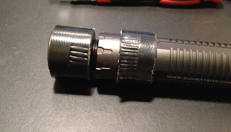
Above you can see that I've got it loose at this point and have it almost completely unscrewed. You can see the marks the pliers left as they bit into the tape. Red loctite is used to hold these pieces together so it does take a bit of force to loosen it.
Below is it apart, the red material in side the threads on the left is the loctite. This should be cleaned up and completely removed. If anyone knows what can be used on threads that's reusable, let me know; I know the screws on my macbook there's some blue stuff that seems to keep them in, and it can be reused. The red locktite should not be reused.
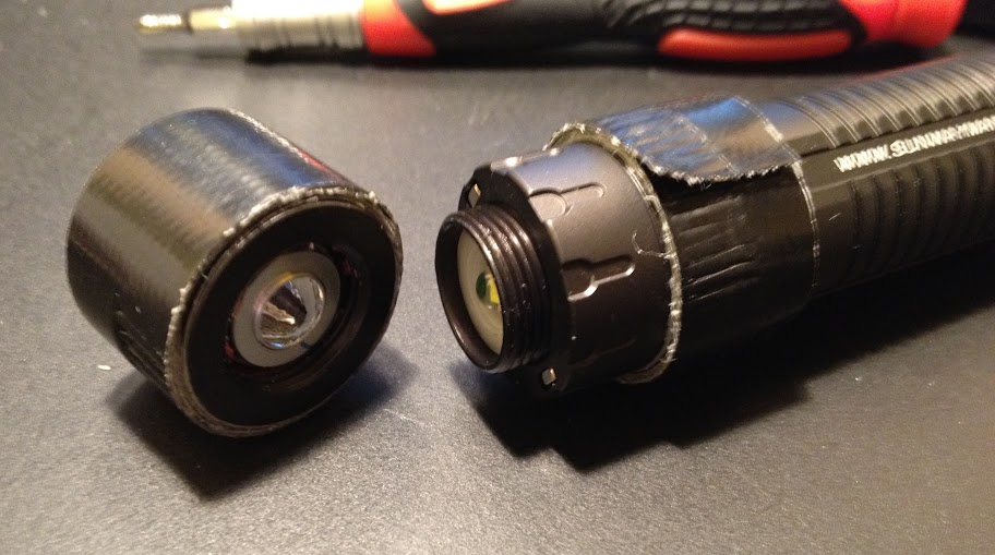
Below is another angle, you can see the layers of tape wrapped around the head and the red loctite.
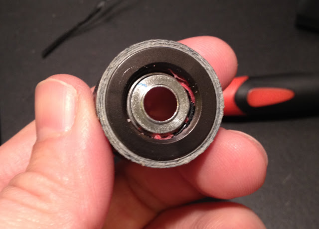
Here is the photo of the base with the tape wrapped around it. The silver rectangular piece is the magnet. There is one on the other side too.

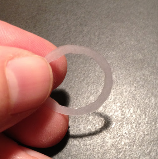
I created a little shim out of some very thin plastic and sanded even thinner to create more pressure between the head and control ring.
Side photo
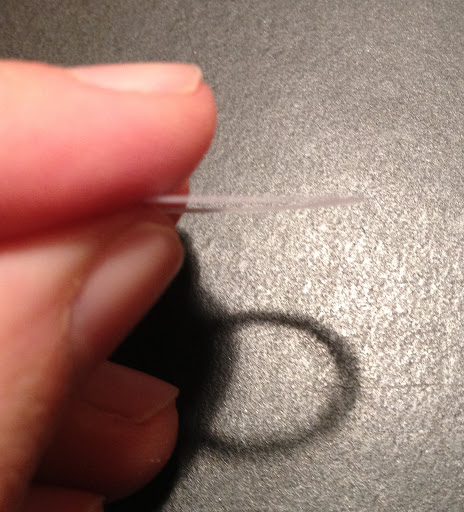
I placed this shim between the control ring and the head to provide more friction. I added a little blue loctite and re-assembled. Now I can adjust the tension on the control ring by how tight I screw the head onto the base
On a side note; there is a metal ring inside the head that is supposed to create the perfect spacing for this, but on mine, this ring is too thick.
http://www.candlepowerforums.com/vb/showthread.php?310269-Sunwayman-V10R-TI-Neutral-XP-G-Mod
I didn't want to make a jig to disassemble it and I also didn't want to heat or torch my light. I found a slightly different way to disassemble that I wanted to share, as well as talk about some of the inner mechanical workings of this light.
Control ring mechanism:
The head of the light presses up against the control ring which rotates to adjust brightness. The ring is not "connected" to anything. There are magnets embedded into the ring which act upon an internal solid state compass. The compass determines at what position the ring is in to adjust the brightness. Very clever.. So,, what was going on here. Since the ring isn't physically connected to anything a thick grease is used to create the friction or resistance you feel when rotating this ring. Again this is very clever.. On mine the head is slightly crooked when screwed on, so at some points during the rotation it became loose.
The head of the light should press against the control ring just enough to keep it pressed against the body, where the layer of the thick, sticky grease that controls the resistance of the movement of the ring.
To take mine apart I used Gorilla tape http://www.gorillaglue.com/tapes.aspx and two adjustable pliers. I ripped around 1/2" strips and wrapped(in the direction that I was going to apply force) them as tightly around the light as possible. I used around 16" of tape, it was just enough to keep the pliers from biting into the body. I performed this with the light completely together and recommend it because it provides support from crushing the parts. Below is the photo where I wrapped the tape. Gorilla tape is like duck tape on steroids, it's much thicker and much stickier.
Above you can see that I've got it loose at this point and have it almost completely unscrewed. You can see the marks the pliers left as they bit into the tape. Red loctite is used to hold these pieces together so it does take a bit of force to loosen it.
Below is it apart, the red material in side the threads on the left is the loctite. This should be cleaned up and completely removed. If anyone knows what can be used on threads that's reusable, let me know; I know the screws on my macbook there's some blue stuff that seems to keep them in, and it can be reused. The red locktite should not be reused.
Below is another angle, you can see the layers of tape wrapped around the head and the red loctite.
Here is the photo of the base with the tape wrapped around it. The silver rectangular piece is the magnet. There is one on the other side too.
I created a little shim out of some very thin plastic and sanded even thinner to create more pressure between the head and control ring.
Side photo
I placed this shim between the control ring and the head to provide more friction. I added a little blue loctite and re-assembled. Now I can adjust the tension on the control ring by how tight I screw the head onto the base
On a side note; there is a metal ring inside the head that is supposed to create the perfect spacing for this, but on mine, this ring is too thick.
Last edited:
")