modamag
Flashlight Enthusiast
Section #1 - Introduction
The purpose of this document is to provide a step by step guide in order to convert your PC power supply into a high current DC power source.
Most PC power supply within the last 10 years will provide at least 100W of power. This will supply more than enough power to operate +3.3V, +5V and +12V DC components such as the Triton battery charger.
Section #2 - Warning & Disclaimer
Power supplies contain electrical hazards which may cause bodily harm or serious injuries. You're performing this modification at your own risk.
Opening a power supply cover will voids any remaining manufacturer or resale warranty.
Never perform work inside the power supply when the power cord is connected to electricity.
Section #3 - Pre-Requisite
This mod is rated at a 2/5 for difficulty. If you can solder and/or cut & strip wires you can do this.
Required Tools:
• 1x Soldering station
• 1x Wire stripper
• 1x Shrink tubing or electrical tape
• 1x Philips screwdriver
• 1x AT/ATX power supply
• 2x 10? 10W power resistor
Optional but Recommended Parts:
• 1x Volt meter
• 1x Power drill
• 1x Crimper / Pliers
• 1x Toggle/pushbutton (SPST) switch
• 4x Banana jack
• 4x 16-14 AWG (blue) ring lug terminal
Section #4 - Functionality Verification (5 minutes)
When selecting a power supply, you want to select one with the highest power rating at the lowest cost possible. Sometime the total power rating is not quite accurate (marketing gimmick). Pay special attention to the "Max Amperage" rating per output voltage. For my power supply its rated 235W but only provide 8A @ +12V, which is more than enough for most application.

Figure 4-1
Since more than likely this unit is a used/old power supply you want to verify that it's still functional.
Precaution: Not all power supply manufacturers follow the industry pin out or color standard.
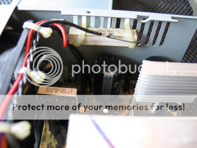
As a safety feature switching power supply require a load on the +5V line to power up. So to trick out the power supply connect the power resistor from +5V to COM to create a dummy load as shown in Figure 4-2.

Figure 4-2
*** ATX Power Supply Only ***
Connect PS_ON (pin14 / green) with COM (pin13 / black) as shown in Figure 4-4.

Figure 4-3

Figure 4-4
Connect the AC power cord, the fan should start spinning. If you have a Volt meter you can now check the output voltage +3.3V (pin1 / orange wire), +5V (pin20 / red wire), and +12V (pin10 / yellow wire). If the fan is not spinning or the voltage is not coming up then the power supply might be bad.
Sectiom #5 - Create Dummy Load (15 minutes)
Using the Philips screwdriver remove the four screws holding the case together.
Get the two power resistor and twist them together so they connect in parallel.
Cut off a +5V (red) wire and solder it to one end of the power resistors. Cut a COM (black) wire and solder it to the other end of the resistors.
Insulate the exposed wires with shrink tubing or electrical tape.
Tip: Cut the wires to 8" length so it's easy to relocate inside the power supply.
Logic: The dummy load (resistor) will experience approximately 5-6W of power. This power is fixed regardless of the resistor size. However, varying the dummy load will result in a change in the output voltage level. P=V2/R
A 10? resistor will carry a load of ~0.6A and provide 11.8V output
Some devices require the voltage to be greater than +12V. In those cases you can just connect two 10? resistors in parallel so the effective resistance is 5? which will change the output voltage to +12.3V.
Mount the resistor to the to the vent holes of the supply casing for heat sinking.
Tip: Do not use wire tie or any plastic tie. These resistors will dissipate enough heat to melt the plastic. Use bare copper wire to tie them to the chassis.
Tip: Mount the resistors as far apart as possible for maximum heat spread.
*** ATX Power Supply Only ***
We need to connect the PS_ON (green) and the COM (black) to the switch.
Logic: Although some power supply may have a rocker switch already installed but we will still need a separate switch for the PS_ON.
The majority of PC power consumption is established at power up. Only a small amount load change will be due to floppy drive, hard drive, and USB/Firewire. So when we turn on our charger there will be a large current draw which could trigger the overload circuitry. So we need to toggle the PS_ON to reset the power supply to apply when this happens.
At this point, the power supply is good to go, providing +3.3V, +5V, and +12V.
But are you satisfied leaving it looking stock like that!? …
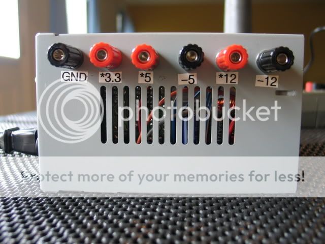
Section #6 - External Banana Jacks (45 minutes)
Now we're going provide some cool external banana jacks for ease of use.
Drill four equally spaced 5/16" hole into the power supply casing.
*** ATX Power Supply Only ***
You should also drill the hole to mount your PW_ON switch at this time. The hole size will be dependent on the switch you have.
Tip: You do not need a drill press for this operation. You can use a cord/cordless hand drill and up size the bit until the desired size have been achieved.
Mount the standoff banana jack at the location of the previously drilled holes.

Figure 6-1
Tip: Use a 7/16" socket for the panel mount nut. Use a 5/32" or 6mm socket for the rear locking nut.
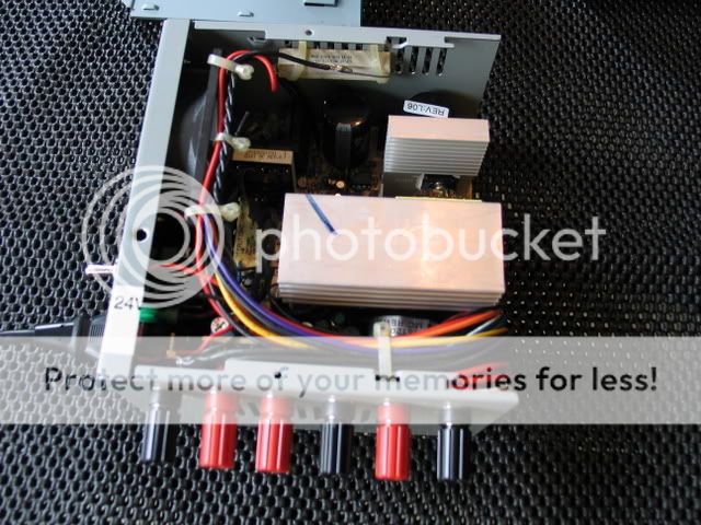
Group all the +3.3V (orange), +5V (red) +12V (yellow) and COM/GND (black) wires together.
Tip: Cut the wire as close to the connector as you can at first, you can shorten them later.
Precaution: Do not attempt to desolder the spare wires from the PC board. You could potentially loosen one of the components and cause your power supply to no longer function properly.
Precaution: For power supply produced after June 2004, you must also connect the remote sense wire (brown) to the +3.3V (orange) wire. Otherwise the power supply will not latch to PWR_ON state.
If your standoff jack provides a solder pad then solder the grouped color wires to the corresponding voltage jack.
Tip: Twist the grouped color wire and tint them. This will make it easier to solder.
If your standoff jack provides a locking nut then grouped the identical color wires together and crimped them to the ring terminal.

Figure 6-2
Mount the ring terminal to the corresponding voltage jack.
Tip: Use at max three wires per connector otherwise you might not be able to properly crimp the connector.
Tip: Use at max two ring terminal per jack otherwise you won't have enough threads to lock them in place.
Section #7 - Reverse Fan Flow
Flip the fan around so that the air is going into the power supply.
Logic: Most power supply fans are designed to draw the hot air from inside the case to the outside. However, for our case the power supply is pretty much the only heat source.
It is much more beneficial to create turbulent flow inside the power supply than laminar flow. This will reduce the localize hot spot.
Section #8 - "Electrify Me!"
*** ATX Power Supply Only ***
Now you will have 4 remaining wires -5V (white), -12V (blue), PWR_OK (gray) and VSB (purple). Since we have no need for these just bend them 180o and insulate them with shrink tubing or electrical tape.

Figure 8-1
Put the power supply back together and tighten the four screws.
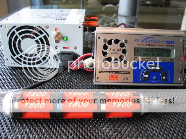
Congratulation! You have just modded yourself a high power DC Power Supply.

Figure 8-2
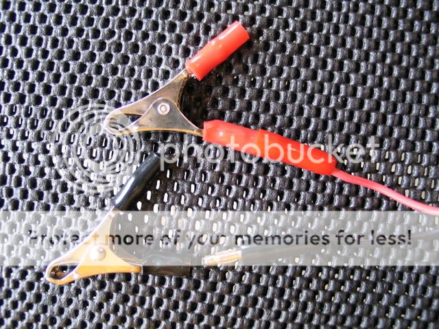
If you have the time, it's also a good idea to make some accessories for your new power supply with the excess connectors.

Figure 8-3
Download offline/printable copy here.
The purpose of this document is to provide a step by step guide in order to convert your PC power supply into a high current DC power source.
Most PC power supply within the last 10 years will provide at least 100W of power. This will supply more than enough power to operate +3.3V, +5V and +12V DC components such as the Triton battery charger.
Section #2 - Warning & Disclaimer
Power supplies contain electrical hazards which may cause bodily harm or serious injuries. You're performing this modification at your own risk.
Opening a power supply cover will voids any remaining manufacturer or resale warranty.
Never perform work inside the power supply when the power cord is connected to electricity.
Section #3 - Pre-Requisite
This mod is rated at a 2/5 for difficulty. If you can solder and/or cut & strip wires you can do this.
Required Tools:
• 1x Soldering station
• 1x Wire stripper
• 1x Shrink tubing or electrical tape
• 1x Philips screwdriver
• 1x AT/ATX power supply
• 2x 10? 10W power resistor
Optional but Recommended Parts:
• 1x Volt meter
• 1x Power drill
• 1x Crimper / Pliers
• 1x Toggle/pushbutton (SPST) switch
• 4x Banana jack
• 4x 16-14 AWG (blue) ring lug terminal
Section #4 - Functionality Verification (5 minutes)
When selecting a power supply, you want to select one with the highest power rating at the lowest cost possible. Sometime the total power rating is not quite accurate (marketing gimmick). Pay special attention to the "Max Amperage" rating per output voltage. For my power supply its rated 235W but only provide 8A @ +12V, which is more than enough for most application.
Figure 4-1
Since more than likely this unit is a used/old power supply you want to verify that it's still functional.
Precaution: Not all power supply manufacturers follow the industry pin out or color standard.
As a safety feature switching power supply require a load on the +5V line to power up. So to trick out the power supply connect the power resistor from +5V to COM to create a dummy load as shown in Figure 4-2.
Figure 4-2
*** ATX Power Supply Only ***
Connect PS_ON (pin14 / green) with COM (pin13 / black) as shown in Figure 4-4.
Figure 4-3
Figure 4-4
Connect the AC power cord, the fan should start spinning. If you have a Volt meter you can now check the output voltage +3.3V (pin1 / orange wire), +5V (pin20 / red wire), and +12V (pin10 / yellow wire). If the fan is not spinning or the voltage is not coming up then the power supply might be bad.
Sectiom #5 - Create Dummy Load (15 minutes)
Using the Philips screwdriver remove the four screws holding the case together.
Get the two power resistor and twist them together so they connect in parallel.
Cut off a +5V (red) wire and solder it to one end of the power resistors. Cut a COM (black) wire and solder it to the other end of the resistors.
Insulate the exposed wires with shrink tubing or electrical tape.
Tip: Cut the wires to 8" length so it's easy to relocate inside the power supply.
Logic: The dummy load (resistor) will experience approximately 5-6W of power. This power is fixed regardless of the resistor size. However, varying the dummy load will result in a change in the output voltage level. P=V2/R
A 10? resistor will carry a load of ~0.6A and provide 11.8V output
Some devices require the voltage to be greater than +12V. In those cases you can just connect two 10? resistors in parallel so the effective resistance is 5? which will change the output voltage to +12.3V.
Mount the resistor to the to the vent holes of the supply casing for heat sinking.
Tip: Do not use wire tie or any plastic tie. These resistors will dissipate enough heat to melt the plastic. Use bare copper wire to tie them to the chassis.
Tip: Mount the resistors as far apart as possible for maximum heat spread.
*** ATX Power Supply Only ***
We need to connect the PS_ON (green) and the COM (black) to the switch.
Logic: Although some power supply may have a rocker switch already installed but we will still need a separate switch for the PS_ON.
The majority of PC power consumption is established at power up. Only a small amount load change will be due to floppy drive, hard drive, and USB/Firewire. So when we turn on our charger there will be a large current draw which could trigger the overload circuitry. So we need to toggle the PS_ON to reset the power supply to apply when this happens.
At this point, the power supply is good to go, providing +3.3V, +5V, and +12V.
But are you satisfied leaving it looking stock like that!? …
Section #6 - External Banana Jacks (45 minutes)
Now we're going provide some cool external banana jacks for ease of use.
Drill four equally spaced 5/16" hole into the power supply casing.
*** ATX Power Supply Only ***
You should also drill the hole to mount your PW_ON switch at this time. The hole size will be dependent on the switch you have.
Tip: You do not need a drill press for this operation. You can use a cord/cordless hand drill and up size the bit until the desired size have been achieved.
Mount the standoff banana jack at the location of the previously drilled holes.
Figure 6-1
Tip: Use a 7/16" socket for the panel mount nut. Use a 5/32" or 6mm socket for the rear locking nut.
Group all the +3.3V (orange), +5V (red) +12V (yellow) and COM/GND (black) wires together.
Tip: Cut the wire as close to the connector as you can at first, you can shorten them later.
Precaution: Do not attempt to desolder the spare wires from the PC board. You could potentially loosen one of the components and cause your power supply to no longer function properly.
Precaution: For power supply produced after June 2004, you must also connect the remote sense wire (brown) to the +3.3V (orange) wire. Otherwise the power supply will not latch to PWR_ON state.
If your standoff jack provides a solder pad then solder the grouped color wires to the corresponding voltage jack.
Tip: Twist the grouped color wire and tint them. This will make it easier to solder.
If your standoff jack provides a locking nut then grouped the identical color wires together and crimped them to the ring terminal.
Figure 6-2
Mount the ring terminal to the corresponding voltage jack.
Tip: Use at max three wires per connector otherwise you might not be able to properly crimp the connector.
Tip: Use at max two ring terminal per jack otherwise you won't have enough threads to lock them in place.
Section #7 - Reverse Fan Flow
Flip the fan around so that the air is going into the power supply.
Logic: Most power supply fans are designed to draw the hot air from inside the case to the outside. However, for our case the power supply is pretty much the only heat source.
It is much more beneficial to create turbulent flow inside the power supply than laminar flow. This will reduce the localize hot spot.
Section #8 - "Electrify Me!"
*** ATX Power Supply Only ***
Now you will have 4 remaining wires -5V (white), -12V (blue), PWR_OK (gray) and VSB (purple). Since we have no need for these just bend them 180o and insulate them with shrink tubing or electrical tape.
Figure 8-1
Put the power supply back together and tighten the four screws.
Congratulation! You have just modded yourself a high power DC Power Supply.
Figure 8-2
If you have the time, it's also a good idea to make some accessories for your new power supply with the excess connectors.
Figure 8-3
Download offline/printable copy here.
Last edited: