ti-force
Flashlight Enthusiast
I really haven't seen anyone using the 7135 drivers to drive the SST-50's or 90's, so I thought I'd share my project with anyone who's interested. WARNING!! PIC HEAVY!!
My original intentions were to build this light to run on 1x26650 from Batteryspace to drive the SST-90 emitter at 5.6A using a 16x7135 driver sandwich with only one mode - BRIGHT. But during the process, I decided that it would be nice to have 3 modes, and I also got a little amp greedy , so I decided to throw one of my Shiningbeam boards into the mix. The Shiningbeam board added an additional 2.8A, and it also added the desired modes of brightness. All of these boards together should have given a combined current of 8.4A, but I had my doubts that the single batteryspace 26650 would supply the current because of voltage sag and a high vf SST-90 emitter, but I decided to try it anyway.
I got a reading of 7.4A at the tail-cap with a freshly topped off 26650. Now, my meter isn't a high dollar meter, so my readings could be off some, and it could be supplying the full 8.4A of current initially, but either way, it falls pretty fast. So I decided to pull two of the AMC7135 boards (8x7135 chips or 2.8A) until I can work out a parallel battery holder for both of my 26650's to run in parallel. I hope this will solve my problem and give me a longer runtime as well.
Anyway, I just thought I'd share some pictures of my mod. I added captions to some of the pics to try and help anyone who has questions:
The first thing I did was disassemble the light and mod the switch assembly and housing:


The second picture up from here suggests soldering the wire to the spring, but since I was only running one battery in my 2d light, I needed something to take up the space. A D sized spacer from Flashlightking does the job nicely. And this is how I implement it into the light (thanks go out to CPF users Linger and Justin Case for their help and ideas with this spacer).
Note: If you're planning to run flat top batteries and you're not planning to run a spacer that has protruding contacts, you may need to trim, saw or grind some of the plastic off of the spring side of the switch housing. If you don't do this, you may not make good contact with the switch.


Then I put the end cap back on the spacer and run the battery positive wire through the spring on the back side of the switch housing and up to the top of the switch housing and solder the wire to the battery positive contact tab. Like this:

Then, on the other side of the switch, I solder another piece of wire to the other positive contact tab. Like this:

I do the same thing with the negative contact point:

Then it's time to reassemble the switch. Like this:

I end up with this:
NOTE: I shortened the negative contact tab after these pics were taken .


Then I build the 7135 slave sandwich:
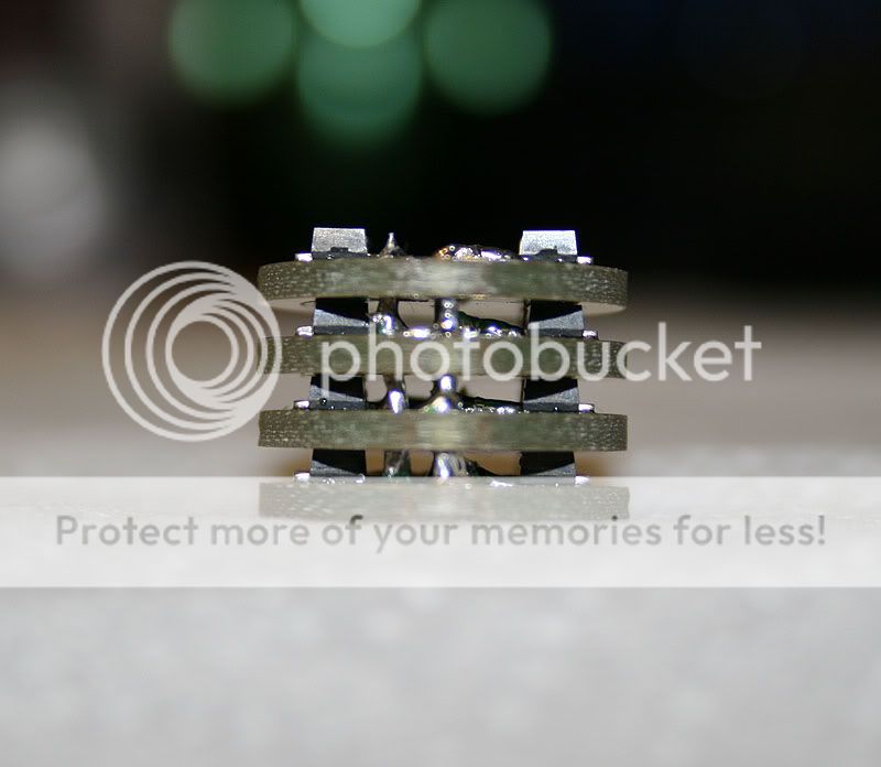

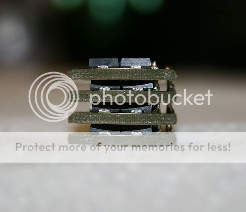
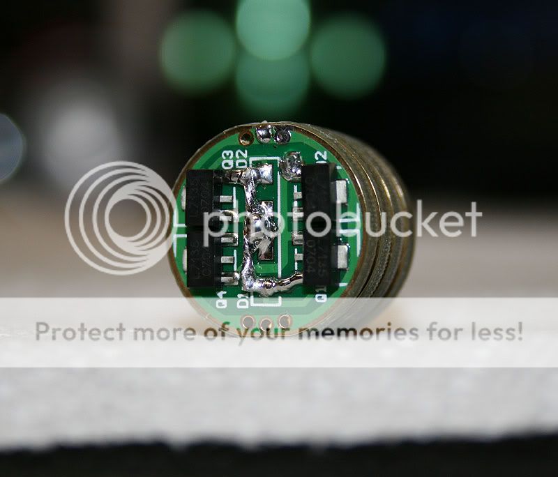
Then I mount the emitter to the heatsink:


A random pic:

And the Shiningbeam driver wired to the slave sandwich and soldered to the emitter:
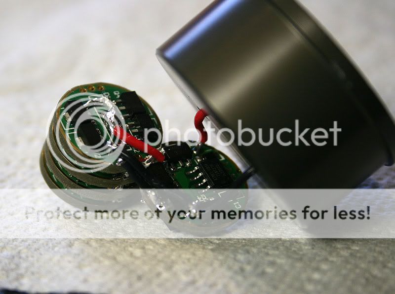
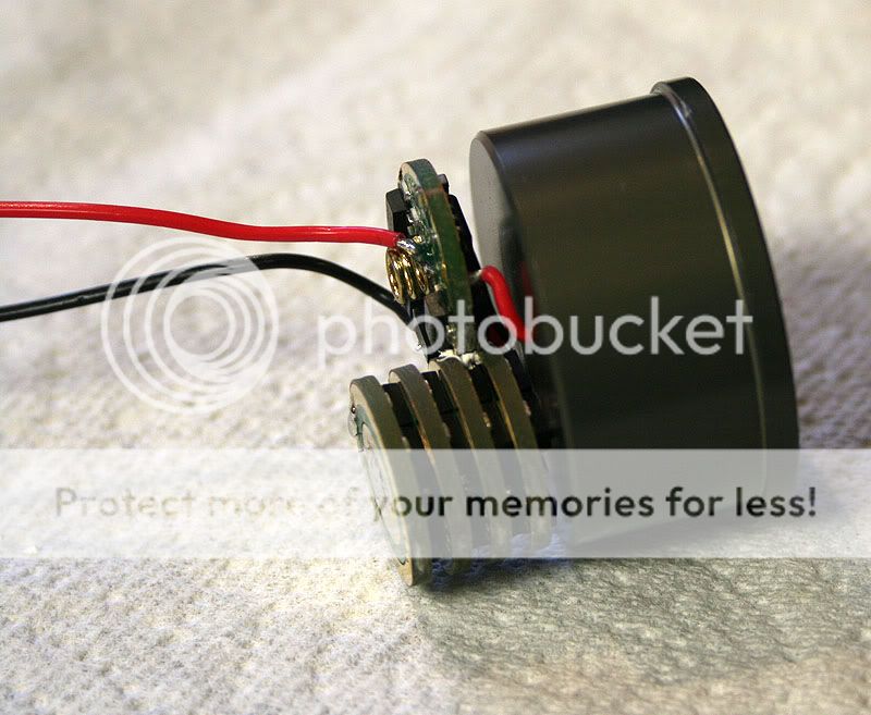
And of course, I couldn't forget the tail-cap spring wire mod:

The battery:

1" shedule 40 PVC pipe for the battery to sit in so there's no rattle:

The beautiful UCL glass from flashlightlens installed:

View from the front:


Next to my SSC P7 Mag:

And a picture of the light:

UCL Glass info:
I was recently asked about the UCL glass in this light. I think is was CPF member Bigchelis who said that OTF lumens would go up by around 10% with the install of the UCL glass. Of course, he also said that your eyes will not actually notice this difference, so it's up to you . I think the UCL glass is made by flashlightlens.com. I purchased mine from CPF vendor Lighthound, click here. The size of the UCL lens is 52.1mm x 1.90mm and it has a light transmittance of 98-99%.
For anyone who's skeptical about the UCL glass because of durability reasons. I'd recommend the acrylic lens from flashlightlens. Click here. It's a little bit thinner than the UCL lens at 52.1mm x 1.68mm, but it's such a small difference; I think it's negligible. It's also lacking about 3-4% in light transmittance (95%) vs the UCL lens (98-99%), but you would never notice this difference with your eyes, again negligible.
Borofloat has also been recommended as an option; it doesn't scratch as easily as the UCL glass. It's manufactured by Schott glass, out of Germany. Most of the high end optics manufacturers use Schott glass, so if you're familiar with good quality rifle scopes and binoculars, you know how nice the upper end glass is.
Heatsink info:
The heatsink I used in this build is an SSC P7 heatsink, with HA111 anodizing. The HA111 anodizing provides electrical insulation for the heatsink, so in the event that a bare wire comes in contact with the heatsink, you don't have to worry about a short. This heatsink was purchased from CPF member H22A, and since it's actually made for an SSC P7 emitter, if you choose to use this heatsink, you will actually have to take a little bit of aluminum out at the top of the pedestal (where the wires are soldered to the bottom of the emitter).
You will also have to center the emitter on your own; the tabs you see on the pedestal are made for a round P7, and as you know, the base on a bare SST-90 is square. I think I read that Setapong (H22A) has some prototype heatsinks for this emitter, but I'm not sure if they're available at the moment. Here's the link to his sales thread: Click here.
CPF member Britelumens also offers heatsinks, and his heatsinks are actually designed to work with the SST-90. Click here for his sales thread.
My original intentions were to build this light to run on 1x26650 from Batteryspace to drive the SST-90 emitter at 5.6A using a 16x7135 driver sandwich with only one mode - BRIGHT. But during the process, I decided that it would be nice to have 3 modes, and I also got a little amp greedy
I got a reading of 7.4A at the tail-cap with a freshly topped off 26650. Now, my meter isn't a high dollar meter, so my readings could be off some, and it could be supplying the full 8.4A of current initially, but either way, it falls pretty fast. So I decided to pull two of the AMC7135 boards (8x7135 chips or 2.8A) until I can work out a parallel battery holder for both of my 26650's to run in parallel. I hope this will solve my problem and give me a longer runtime as well.
Anyway, I just thought I'd share some pictures of my mod. I added captions to some of the pics to try and help anyone who has questions:
The first thing I did was disassemble the light and mod the switch assembly and housing:


The second picture up from here suggests soldering the wire to the spring, but since I was only running one battery in my 2d light, I needed something to take up the space. A D sized spacer from Flashlightking does the job nicely. And this is how I implement it into the light (thanks go out to CPF users Linger and Justin Case for their help and ideas with this spacer).
Note: If you're planning to run flat top batteries and you're not planning to run a spacer that has protruding contacts, you may need to trim, saw or grind some of the plastic off of the spring side of the switch housing. If you don't do this, you may not make good contact with the switch.


Then I put the end cap back on the spacer and run the battery positive wire through the spring on the back side of the switch housing and up to the top of the switch housing and solder the wire to the battery positive contact tab. Like this:

Then, on the other side of the switch, I solder another piece of wire to the other positive contact tab. Like this:

I do the same thing with the negative contact point:

Then it's time to reassemble the switch. Like this:

I end up with this:
NOTE: I shortened the negative contact tab after these pics were taken .


Then I build the 7135 slave sandwich:


Then I mount the emitter to the heatsink:


A random pic:

And the Shiningbeam driver wired to the slave sandwich and soldered to the emitter:


And of course, I couldn't forget the tail-cap spring wire mod:

The battery:

1" shedule 40 PVC pipe for the battery to sit in so there's no rattle:

The beautiful UCL glass from flashlightlens installed:

View from the front:


Next to my SSC P7 Mag:

And a picture of the light:

UCL Glass info:
I was recently asked about the UCL glass in this light. I think is was CPF member Bigchelis who said that OTF lumens would go up by around 10% with the install of the UCL glass. Of course, he also said that your eyes will not actually notice this difference, so it's up to you
For anyone who's skeptical about the UCL glass because of durability reasons. I'd recommend the acrylic lens from flashlightlens. Click here. It's a little bit thinner than the UCL lens at 52.1mm x 1.68mm, but it's such a small difference; I think it's negligible. It's also lacking about 3-4% in light transmittance (95%) vs the UCL lens (98-99%), but you would never notice this difference with your eyes, again negligible.
Borofloat has also been recommended as an option; it doesn't scratch as easily as the UCL glass. It's manufactured by Schott glass, out of Germany. Most of the high end optics manufacturers use Schott glass, so if you're familiar with good quality rifle scopes and binoculars, you know how nice the upper end glass is.
Heatsink info:
The heatsink I used in this build is an SSC P7 heatsink, with HA111 anodizing. The HA111 anodizing provides electrical insulation for the heatsink, so in the event that a bare wire comes in contact with the heatsink, you don't have to worry about a short. This heatsink was purchased from CPF member H22A, and since it's actually made for an SSC P7 emitter, if you choose to use this heatsink, you will actually have to take a little bit of aluminum out at the top of the pedestal (where the wires are soldered to the bottom of the emitter).
You will also have to center the emitter on your own; the tabs you see on the pedestal are made for a round P7, and as you know, the base on a bare SST-90 is square. I think I read that Setapong (H22A) has some prototype heatsinks for this emitter, but I'm not sure if they're available at the moment. Here's the link to his sales thread: Click here.
CPF member Britelumens also offers heatsinks, and his heatsinks are actually designed to work with the SST-90. Click here for his sales thread.
Last edited:


 ) "L" shaped bit that is also epoxied to the emitter heatsink or inside the flashlight body. Just a little bit of thermal protection. Heat should not be an issue with 3 D NiMH cells, single lithium, or parallel lithiums.

 and then brightness would fall off, WAY off:mecry:.