Alan B
Flashlight Enthusiast
Hotwire Regulator Design Collaboration Project part 2
The Programmable Hotwire Driver, as it has come to be called, has spawned some application specific projects. Basic design continues in this thread, and specific implementation threads are linked at the bottom of this posting.
The third section of this design thread continues here: https://www.candlepowerforums.com/posts/2803333
Now on to this, the second half of the Design thread:
(From the first post of the first thread, with changes")
Now that I've built a M@g85 I can see the value of a soft starting regulator for incan. But I don't see much availability. I see JimmyM and AW planning to do something soon. I see old stuff but not currently available. Did I miss any? Soft starting with a thermistor is nice, but not enough.
Being the electronics and software engineer that I am makes me think of how to build a simple regulator. With today's microprocessors having PWM, ADCs, temperature detection and just about everything else (memory, clock, ram, etc) built in, it would seem to me that very few parts are required. I have done projects with AVR and PIC microprocessors. It is amazing what can be done with a single small low lead-count chip. (The design developed here uses only about a dozen parts).
Requirements that I would like to see:
Primary Features:
1) soft start
2) regulated RMS bulb voltage by PWM for high efficiency
3) provide battery overdischarge protection
4) provide overtemperature protection for the electronics
5) provide selectable voltage levels (programmable Vbulb)
(10/4/08, above items are coded and tested, the FET power driver is tested)
6) have a lock off sequence for safety - secret unlock sequence to prevent accidental turnon (or provide a 'normal' flashlight Vbulb mode that would run the bulb at a lower setting that is very safe, and keep the turbo mode for expert access)
7) provide a 'timeout' feature to dim and shutdown to limit runtimes when desired
8) make it user reprogrammable, with free software tools and simple/inexpensive PC interface
9) have some public open sourcecode so folks could play with the user interface and make customized versions
10) have a public pcb layout available so folks could roll their own small batch if needed
11) one or more folks can make the hardware (and sell it), over time if they become unavailable someone new can step in and make hardware that will work with the same or slightly modified software
12) be a simple enough design to allow a builder to make one without a pcb (DIY dead-bug style, etc)
Secondary Features (possibly developed later):
1) provide one button reprogramming in the field for voltage settings, etc
2) provide a minimum off timer to reduce bulb wear from over clicking friends
3) auto-detect battery type and set voltage protection
4) other ideas??
It seems to me that it would not take a lot of parts to do this. A good Power FET directly driven from an AVR or PIC micro PWM output, and a way to measure the actual voltage across the filament, plus some calculations to determine the effective (RMS) voltage and adjust smoothly to the desired value. Possibly a second ADC channel on the battery side to keep track of the battery voltage (if needed). Approximately three processor I/O pins are required:
1) pushbutton input (option, some designs don't need this)(need on-switch detection in some cases)
2) pwm out
3) battery voltage (loaded battery V is bulb peak V)
-) bulb RMS voltage (calculate from bulb peak V and duty cycle of PWM)
This would place square wave current pulses into the filament, but the frequency can be selected to be high enough to avoid problems, but low enough to manage losses in the switching FET. The thermal inertia of the filament provides the filtering, so pulses must be short enough for the temperature to be essentially constant from pulse to pulse.
I don't know if any of the existing available designs work precisely this way. JimmyM's soft start is not a micro. AW's is but I don't know much about the design. Most others I find (AWR et al) are no longer available.
Anyone interested in something like this? I don't have the time to do the whole project, but I may be able to do some part of it. Perhaps it could be some kind of group project?
Any interest? Any important requirements or concerns about this simple approach?? Anyone want to work on this???
If you have any links to similar projects (past or present), post them in this thread so we can review them and give them credit.
If you have done similar work or have ideas, chime in and let us know!
-- Alan
Today (10/4/2008) we start part 2 of the thread.
Part 1 is here:
https://www.candlepowerforums.com/threads/186291
Part 3 is here:
https://www.candlepowerforums.com/posts/2803333
Project Status: (10/4/2008)
We have a schematic and two circuit boards have been designed. One has been produced and tested. See the directory linked below. We have a sketch of a "Regulator Sled" that would slide into a D mag and replace the switch with the regulator PCB and a tactile momentary switch. There can be other electrical and mechanical designs, but this is what we have thus far.
Project Status: (12/2008)
wquiles and JimmyM have started application specific projects for derivative versions of what has come to be known as the PHD (Programmable Hotwire Driver) regulator, and have threads pertaining to the details. General and specific design discussions continue in this thread. Links to the new threads are at the bottom of this posting. JimmyM has released a development/test PC board.
Project Status: (1/2009)
Alan has built a prototype into a D M@g and is about to build and test the second generation PCB for the M@gSled. There is an interest thread for that variant as well as JimmyM and wquiles versions.
Schematic
http://akbeng.com/flash/hwreg/hrdc1d.bmp
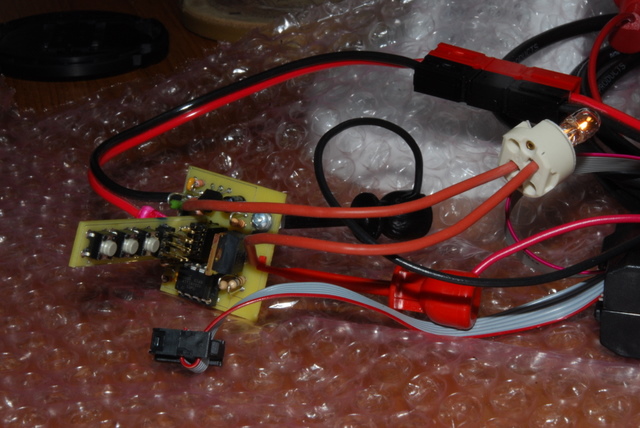
We have Code and Hardware Working:
The above is an actual scope capture of the output of the CPU driving PWM to the FET gate (in blue), and the output of the FET (in red) while driving a WA1185 bulb on Alan's test M@G D Sled prototype PC Board.
We have prototype hardware running. Alan B's sled board, and wquiles' protoboard. At this point (10/4/2008) we are working on software and calibration, and have worked through a couple of minor problems. Alan built and tested the USBtinyISP programmer. This is a $22 kit for programming the micro. This will be useful for loading the software, changing the parameters, and trying out different versions of the software. Advanced users and builders will want a programmer to have complete control over the software in their flashlights.
Alan has developed software using the Atmel STK500 board. This board has the programming capability, a socket for the CPU, and an LED and switch that can be jumpered to the chip. Using this Alan has developed software that does most of the basic functions - variable levels, voltage regulation, temperature and low battery cutout, etc. This is still in work, but it is doing most of the important functions required for this project.
Prototypes of the hardware are working. JimmyM and Alan are both working on pc boards. Alan's board is made and working, and Jim's test board is designed but not cut yet.
We have a couple of user interfaces including VariLevel Ramped with optional double-click boost, and On/Off. We have soft start. We have RMS feedback regulation.
Next Step:
The calibration problem appears to be solved, so it is about time to package this in a flashlight, and make some 'operational' software versions. The dynamic calibration needs to be finished up. Perhaps a multilevel interface option would be useful. Possibly one or more small PCBs designed to fit inside "C", "D" M@gs or SF M6's. High Power bulb testing would be interesting. Will wants to work on a one button interface and a SF M6 version. Jim wants to try a "high power" version with a driver.
Signup Sheet:
Send me a pm if you want to be added to this list:
Hardware Design: mostly done, here on the forum, by Alan B, JimmyM and That_Guy; with lots of helpful input and encouragement by folks like LuxLuthor, and others.
Hardware Prototyping: Alan B, JimmyM and wquiles working on.
Application Specific versions - wquiles is working on the SF M6 version, and JimmyM is working on a D M@G version to fit under a KIU base.
High Power Testing - Possibly Jim and LuxLuthor?
Software Development: The software is pretty far along at this point. Based on AVR-GCC in WinAVR and AVR Studio for this. All Free software tools. Thus far Software is by Alan B with input and feedback from lots of others.
Test Programs: (these are done)
* FP1: Toggle the FET Gate Output (very slow or 100 hz, 50% duty cycle)
* FP2: Electronic Pushbutton Switch (on/off)
* FP3: Always On, Fixed PWM, Soft Start
* FP4: Pushbutton, Fixed PWM, Soft Start
* FP5: Pushbutton, VariLevel PWM, Soft Start
* FP6: Always On, Regulated, Calibrated, Soft Start
* FP7: Pushbutton, Regulated, Calibrated, Soft Start
* FP8: Test Suite for ADC, PWM, Regulation Algorithms
* FP9: Functional Flashlight Control program with many features
More to come.
Design File Area: (schematics, code, scope traces, data)
http://akbeng.com/flash/hwreg/
References:
The Lightbrain 2002 DIY regulator is very similar to the design goals for this project:
http://lasertagparts.com/lightbrain/free_regulator.htm
AWR HotDriver (soft start, linear):
http://www.cpfmarketplace.com/mp/showthread.php?t=107783
PIR1 PWM Regulator Thread:
https://www.candlepowerforums.com/threads/107211
PIR1 Regulator Manual:
http://greenengineering.se/PIR1/PIRmanual.pdf
Willie Hunt Light Bulb Regulator:
http://www.cs.indiana.edu/~willie/lvr.html
That_Guy Regulator (similar to LightBrain):
http://img169.imageshack.us/img169/5875/pwmregulatorff7.png
http://rapidshare.com/files/87979929/PWM_Regulator.zip.html
JimmyM JM-SST Soft Start:
https://www.candlepowerforums.com/threads/181866
AW Soft Start:
http://candlepowerforums.com/vb/showthread.php?t=166223
Kiu Bipin Socket:
https://www.candlepowerforums.com/threads/171607
(Destructive) Bulb Testing - lots of bulb data:
https://www.candlepowerforums.com/threads/179748
More Bulb Data (for the SF M6, but useful for others):
https://www.candlepowerforums.com/threads/204157
Atmel Tiny85 Microprocessor Info:
http://www.atmel.com/dyn/products/product_card.asp?part_id=3612
Atmel AVR ISP USB Programming Adapter:
http://search.digikey.com/scripts/DkSearch/dksus.dll?Detail?name=ATAVRISP2-ND
AvrFreaks on the Tiny85:
http://www.avrfreaks.net/index.php?module=Freaks Devices&func=displayDev&objectid=102
Low Cost USB programmer (tested, works):
http://www.ladyada.net/make/usbtinyisp/
AvrDude Programming Software (included in WinAVR):
http://www.ladyada.net/make/usbtinyisp/avrdude.html
Application Projects based on this Project's Design:
D M@g Drop-in by Alan B:
https://www.candlepowerforums.com/threads/218506
SF M6 thread by wquiles:
https://www.candlepowerforums.com/threads/215806
D M@g under Kiu Base thread by JimmyM:
https://www.candlepowerforums.com/posts/2743186
eof
The Programmable Hotwire Driver, as it has come to be called, has spawned some application specific projects. Basic design continues in this thread, and specific implementation threads are linked at the bottom of this posting.
The third section of this design thread continues here: https://www.candlepowerforums.com/posts/2803333
Now on to this, the second half of the Design thread:
(From the first post of the first thread, with changes
Now that I've built a M@g85 I can see the value of a soft starting regulator for incan. But I don't see much availability. I see JimmyM and AW planning to do something soon. I see old stuff but not currently available. Did I miss any? Soft starting with a thermistor is nice, but not enough.
Being the electronics and software engineer that I am makes me think of how to build a simple regulator. With today's microprocessors having PWM, ADCs, temperature detection and just about everything else (memory, clock, ram, etc) built in, it would seem to me that very few parts are required. I have done projects with AVR and PIC microprocessors. It is amazing what can be done with a single small low lead-count chip. (The design developed here uses only about a dozen parts).
Requirements that I would like to see:
Primary Features:
1) soft start
2) regulated RMS bulb voltage by PWM for high efficiency
3) provide battery overdischarge protection
4) provide overtemperature protection for the electronics
5) provide selectable voltage levels (programmable Vbulb)
(10/4/08, above items are coded and tested, the FET power driver is tested)
6) have a lock off sequence for safety - secret unlock sequence to prevent accidental turnon (or provide a 'normal' flashlight Vbulb mode that would run the bulb at a lower setting that is very safe, and keep the turbo mode for expert access)
7) provide a 'timeout' feature to dim and shutdown to limit runtimes when desired
8) make it user reprogrammable, with free software tools and simple/inexpensive PC interface
9) have some public open sourcecode so folks could play with the user interface and make customized versions
10) have a public pcb layout available so folks could roll their own small batch if needed
11) one or more folks can make the hardware (and sell it), over time if they become unavailable someone new can step in and make hardware that will work with the same or slightly modified software
12) be a simple enough design to allow a builder to make one without a pcb (DIY dead-bug style, etc)
Secondary Features (possibly developed later):
1) provide one button reprogramming in the field for voltage settings, etc
2) provide a minimum off timer to reduce bulb wear from over clicking friends
3) auto-detect battery type and set voltage protection
4) other ideas??
It seems to me that it would not take a lot of parts to do this. A good Power FET directly driven from an AVR or PIC micro PWM output, and a way to measure the actual voltage across the filament, plus some calculations to determine the effective (RMS) voltage and adjust smoothly to the desired value. Possibly a second ADC channel on the battery side to keep track of the battery voltage (if needed). Approximately three processor I/O pins are required:
1) pushbutton input (option, some designs don't need this)(need on-switch detection in some cases)
2) pwm out
3) battery voltage (loaded battery V is bulb peak V)
-) bulb RMS voltage (calculate from bulb peak V and duty cycle of PWM)
This would place square wave current pulses into the filament, but the frequency can be selected to be high enough to avoid problems, but low enough to manage losses in the switching FET. The thermal inertia of the filament provides the filtering, so pulses must be short enough for the temperature to be essentially constant from pulse to pulse.
I don't know if any of the existing available designs work precisely this way. JimmyM's soft start is not a micro. AW's is but I don't know much about the design. Most others I find (AWR et al) are no longer available.
Anyone interested in something like this? I don't have the time to do the whole project, but I may be able to do some part of it. Perhaps it could be some kind of group project?
Any interest? Any important requirements or concerns about this simple approach?? Anyone want to work on this???
If you have any links to similar projects (past or present), post them in this thread so we can review them and give them credit.
If you have done similar work or have ideas, chime in and let us know!
-- Alan
Today (10/4/2008) we start part 2 of the thread.
Part 1 is here:
https://www.candlepowerforums.com/threads/186291
Part 3 is here:
https://www.candlepowerforums.com/posts/2803333
Project Status: (10/4/2008)
We have a schematic and two circuit boards have been designed. One has been produced and tested. See the directory linked below. We have a sketch of a "Regulator Sled" that would slide into a D mag and replace the switch with the regulator PCB and a tactile momentary switch. There can be other electrical and mechanical designs, but this is what we have thus far.
Project Status: (12/2008)
wquiles and JimmyM have started application specific projects for derivative versions of what has come to be known as the PHD (Programmable Hotwire Driver) regulator, and have threads pertaining to the details. General and specific design discussions continue in this thread. Links to the new threads are at the bottom of this posting. JimmyM has released a development/test PC board.
Project Status: (1/2009)
Alan has built a prototype into a D M@g and is about to build and test the second generation PCB for the M@gSled. There is an interest thread for that variant as well as JimmyM and wquiles versions.
Schematic
http://akbeng.com/flash/hwreg/hrdc1d.bmp
We have Code and Hardware Working:
The above is an actual scope capture of the output of the CPU driving PWM to the FET gate (in blue), and the output of the FET (in red) while driving a WA1185 bulb on Alan's test M@G D Sled prototype PC Board.
We have prototype hardware running. Alan B's sled board, and wquiles' protoboard. At this point (10/4/2008) we are working on software and calibration, and have worked through a couple of minor problems. Alan built and tested the USBtinyISP programmer. This is a $22 kit for programming the micro. This will be useful for loading the software, changing the parameters, and trying out different versions of the software. Advanced users and builders will want a programmer to have complete control over the software in their flashlights.
Alan has developed software using the Atmel STK500 board. This board has the programming capability, a socket for the CPU, and an LED and switch that can be jumpered to the chip. Using this Alan has developed software that does most of the basic functions - variable levels, voltage regulation, temperature and low battery cutout, etc. This is still in work, but it is doing most of the important functions required for this project.
Prototypes of the hardware are working. JimmyM and Alan are both working on pc boards. Alan's board is made and working, and Jim's test board is designed but not cut yet.
We have a couple of user interfaces including VariLevel Ramped with optional double-click boost, and On/Off. We have soft start. We have RMS feedback regulation.
Next Step:
The calibration problem appears to be solved, so it is about time to package this in a flashlight, and make some 'operational' software versions. The dynamic calibration needs to be finished up. Perhaps a multilevel interface option would be useful. Possibly one or more small PCBs designed to fit inside "C", "D" M@gs or SF M6's. High Power bulb testing would be interesting. Will wants to work on a one button interface and a SF M6 version. Jim wants to try a "high power" version with a driver.
Signup Sheet:
Send me a pm if you want to be added to this list:
Hardware Design: mostly done, here on the forum, by Alan B, JimmyM and That_Guy; with lots of helpful input and encouragement by folks like LuxLuthor, and others.
Hardware Prototyping: Alan B, JimmyM and wquiles working on.
Application Specific versions - wquiles is working on the SF M6 version, and JimmyM is working on a D M@G version to fit under a KIU base.
High Power Testing - Possibly Jim and LuxLuthor?
Software Development: The software is pretty far along at this point. Based on AVR-GCC in WinAVR and AVR Studio for this. All Free software tools. Thus far Software is by Alan B with input and feedback from lots of others.
Test Programs: (these are done)
* FP1: Toggle the FET Gate Output (very slow or 100 hz, 50% duty cycle)
* FP2: Electronic Pushbutton Switch (on/off)
* FP3: Always On, Fixed PWM, Soft Start
* FP4: Pushbutton, Fixed PWM, Soft Start
* FP5: Pushbutton, VariLevel PWM, Soft Start
* FP6: Always On, Regulated, Calibrated, Soft Start
* FP7: Pushbutton, Regulated, Calibrated, Soft Start
* FP8: Test Suite for ADC, PWM, Regulation Algorithms
* FP9: Functional Flashlight Control program with many features
More to come.
Design File Area: (schematics, code, scope traces, data)
http://akbeng.com/flash/hwreg/
References:
The Lightbrain 2002 DIY regulator is very similar to the design goals for this project:
http://lasertagparts.com/lightbrain/free_regulator.htm
AWR HotDriver (soft start, linear):
http://www.cpfmarketplace.com/mp/showthread.php?t=107783
PIR1 PWM Regulator Thread:
https://www.candlepowerforums.com/threads/107211
PIR1 Regulator Manual:
http://greenengineering.se/PIR1/PIRmanual.pdf
Willie Hunt Light Bulb Regulator:
http://www.cs.indiana.edu/~willie/lvr.html
That_Guy Regulator (similar to LightBrain):
http://img169.imageshack.us/img169/5875/pwmregulatorff7.png
http://rapidshare.com/files/87979929/PWM_Regulator.zip.html
JimmyM JM-SST Soft Start:
https://www.candlepowerforums.com/threads/181866
AW Soft Start:
http://candlepowerforums.com/vb/showthread.php?t=166223
Kiu Bipin Socket:
https://www.candlepowerforums.com/threads/171607
(Destructive) Bulb Testing - lots of bulb data:
https://www.candlepowerforums.com/threads/179748
More Bulb Data (for the SF M6, but useful for others):
https://www.candlepowerforums.com/threads/204157
Atmel Tiny85 Microprocessor Info:
http://www.atmel.com/dyn/products/product_card.asp?part_id=3612
Atmel AVR ISP USB Programming Adapter:
http://search.digikey.com/scripts/DkSearch/dksus.dll?Detail?name=ATAVRISP2-ND
AvrFreaks on the Tiny85:
http://www.avrfreaks.net/index.php?module=Freaks Devices&func=displayDev&objectid=102
Low Cost USB programmer (tested, works):
http://www.ladyada.net/make/usbtinyisp/
AvrDude Programming Software (included in WinAVR):
http://www.ladyada.net/make/usbtinyisp/avrdude.html
Application Projects based on this Project's Design:
D M@g Drop-in by Alan B:
https://www.candlepowerforums.com/threads/218506
SF M6 thread by wquiles:
https://www.candlepowerforums.com/threads/215806
D M@g under Kiu Base thread by JimmyM:
https://www.candlepowerforums.com/posts/2743186
eof
Last edited: