• You must be a Supporting Member to participate in the Candle Power Forums Marketplace.

    You can become a Supporting Member.

Sold/Expired Custom McG45's for sale ...

wquiles

Flashaholic
Joined
Jan 10, 2005
Messages
8,459
Location
Texas, USA, Earth
A few more photos:

That new glass looks pretty invisible, doesn't?
IMG_7029.JPG


If you change the angle just right, you can see that all those 4 heads had the UCL glass in them ;)
IMG_7030.JPG


With help from some aluminum parts from Mirage_Man and some time in my lathe, I am working on a new variation of the heatsink for these 4 custom lights. Once I get the drivers from George, I will be able to do the final fitting:
IMG_7055.JPG


Hang in there guys - these lights are coming together just fine :D

Will
 

wquiles

Flashaholic
Joined
Jan 10, 2005
Messages
8,459
Location
Texas, USA, Earth
Another update!

George just finished the first batch of drivers and I was able to get enough from George for this build. Once I get them (probably no later than next week) I will be able to complete each light, one at a time. I will post here again as they get ready ;)

Thanks much for your patience :D

Will
 

wquiles

Flashaholic
Joined
Jan 10, 2005
Messages
8,459
Location
Texas, USA, Earth
OK folks, lights are starting to come together now that I have the drivers!!!

IMG_7198.JPG


I finished fitting all 4 reflectors to their new heads:
IMG_7201.JPG


IMG_7203.JPG


IMG_7205.JPG


IMG_7206.JPG


Today I started the fitting of the HS and the plastic washer that prevents the head from crushing the LED:
IMG_7204.JPG


IMG_7208.JPG


Will
 

wquiles

Flashaholic
Joined
Jan 10, 2005
Messages
8,459
Location
Texas, USA, Earth
OK, more pictures from today!

Today I worked in turning the switches from ON-OFF to momentary on, which is what is needed for the drivers from George which need a momentary switch to go to ground to be activated.

In the photos below you can see that the botton contact on the switch is now negative (ground in our system) so when the button is pressed, it provides a ground to activate the switch. The switch input to the converter will now come from the old positive contact at the top of the switch. There are probably other ways to do this, but this is the one I picked ;)

Routing for the wires:
IMG_7210.JPG


IMG_7213.JPG


Eliminating the ON-OFF, by going from this:
IMG_7227.JPG


to this:
IMG_7219.JPG


Epoxying the new positive contact - note that solder blob is higher in the middle, so even flat top cells will work properly here - no magnets needed!:
IMG_7226.JPG


IMG_7209.JPG


I got two switches done today:
IMG_7228.JPG


Almost there - thanks again for your patience guys ;)

Will
 
Last edited:

wquiles

Flashaholic
Joined
Jan 10, 2005
Messages
8,459
Location
Texas, USA, Earth
OK guys, I think that this is "the" weekend to finish the lights :party:

I have a few minor steps before soldering the drivers, dry-testing all connections, secure the drivers, and do final assembly :D

The only light that will take longer to finish is the 2xC since this uses the bFlex (round nFlex) and it will take some additional fitting due to the board being bigger than the MaxiFlex. But no worries, we are almost there folks !!!

IMG_7260.JPG


IMG_7261.JPG


IMG_7264.JPG


IMG_7265.JPG


Will
 

wquiles

Flashaholic
Joined
Jan 10, 2005
Messages
8,459
Location
Texas, USA, Earth
Great progress today. More pictures :naughty:

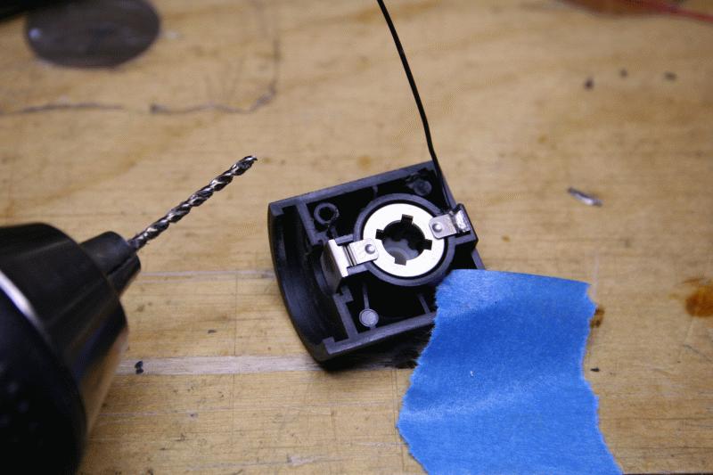
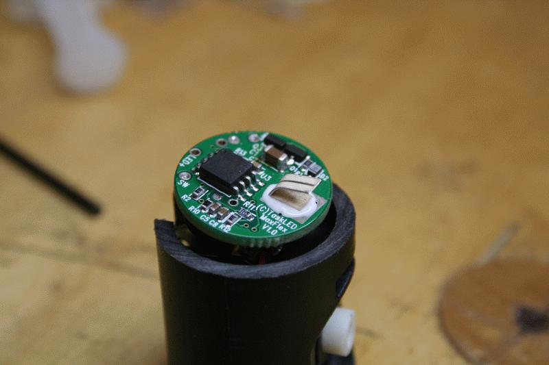
Starting to wire drivers:
IMG_7266.JPG


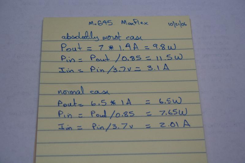
Calculated power to see if I needed additional heatsinking on the MaxFlex. Although my design goal has been for 1.0Amps, these drivers can deliver up to 1.4Amps, so it looks like I will be making these 1xC McG45's a little bit more robust just in case you crazy owners decide to want "more" :grin2:
IMG_7269.JPG


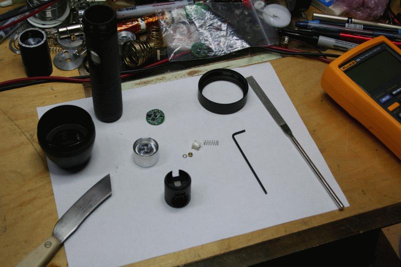
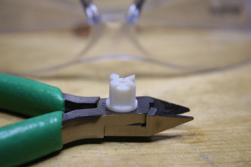
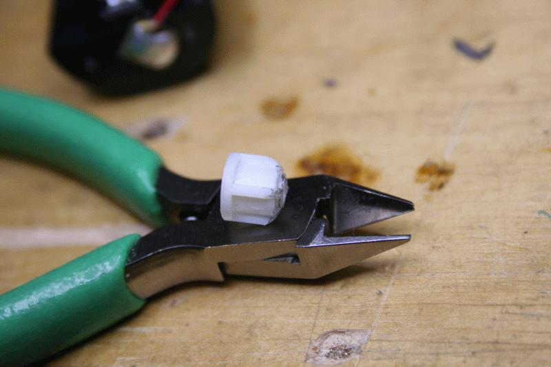
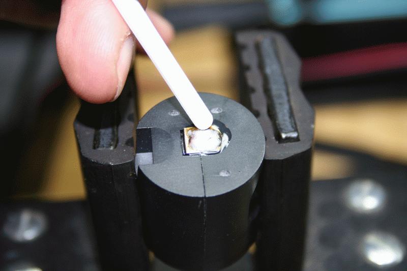
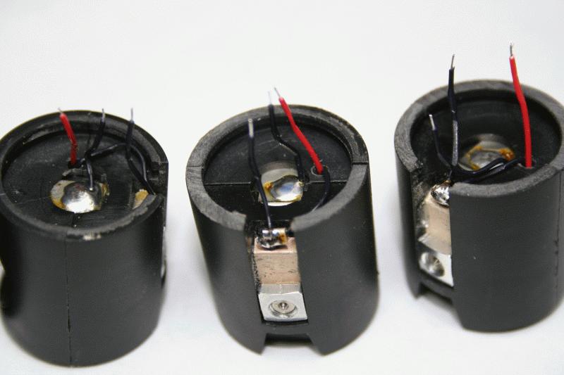
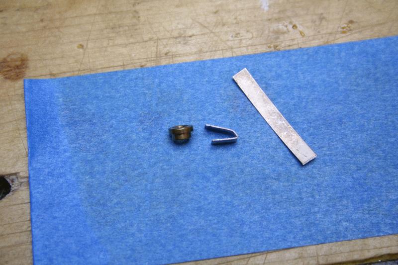
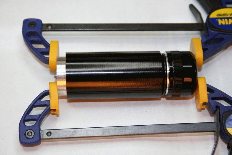
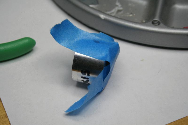
So I found out how to get a metal "spring" with thermal AA on both sides to attach to the thermal pad George provided on the MaxFlex:
IMG_7271.JPG


IMG_7272.JPG


IMG_7274.JPG


IMG_7276.JPG


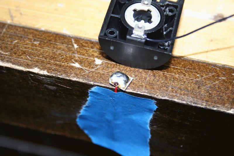
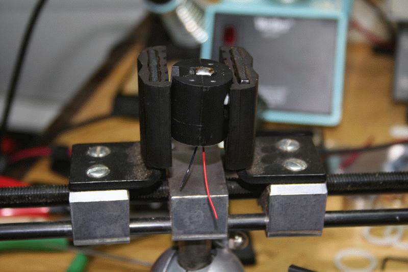
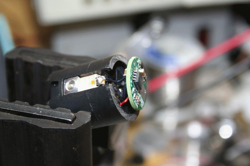
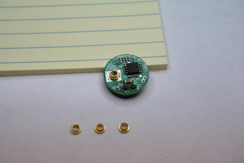
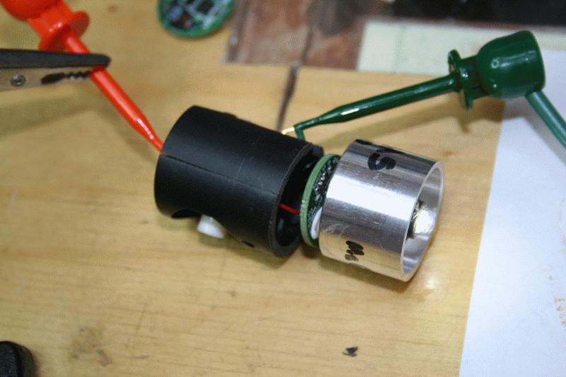
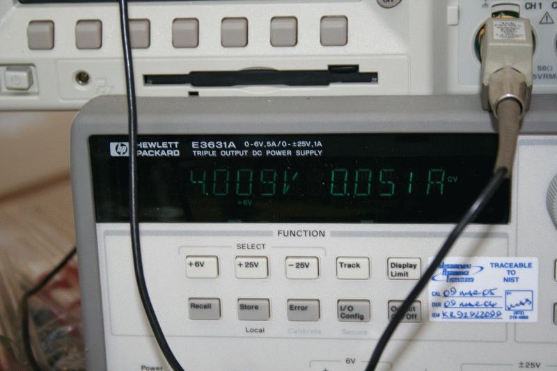
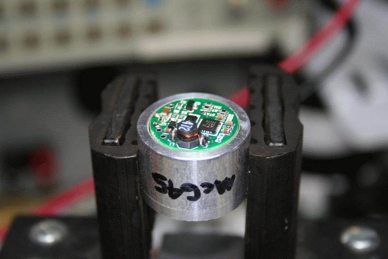
Before I glued the converter to the HS, I tested it, of course!. As expected, the light came up at its default value of 350mA, which at its lowest level draws 50mA from a 4V supply:
IMG_7280.JPG


IMG_7281.JPG


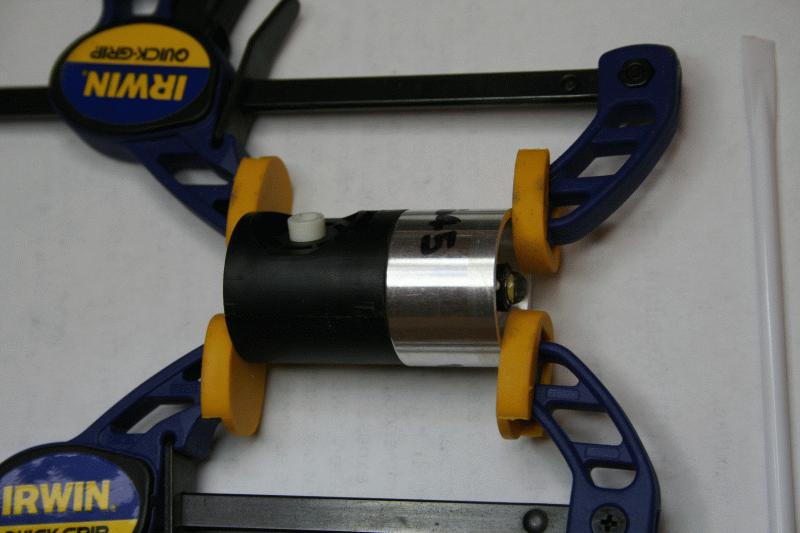
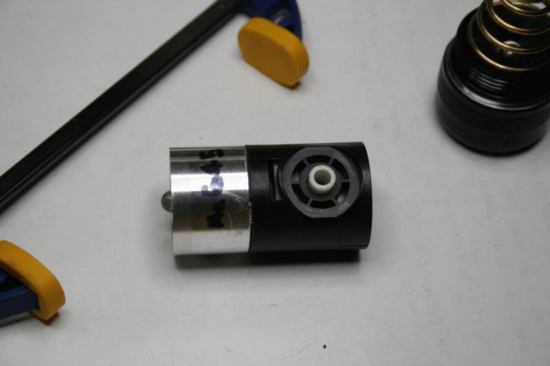
Then glue the converter:
IMG_7282.JPG


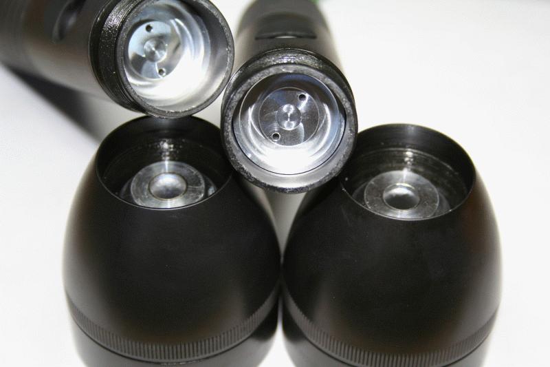
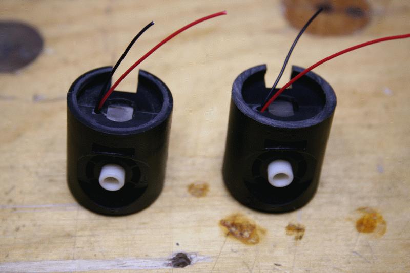
and then glue the HS to the switch:
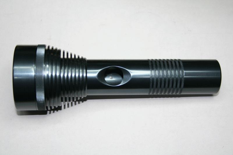
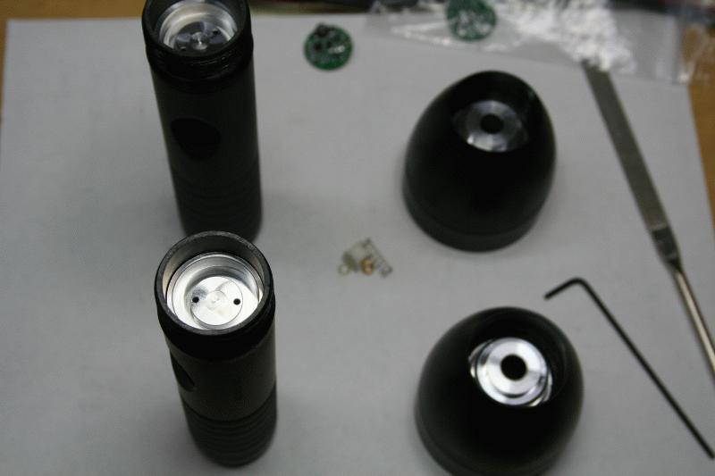
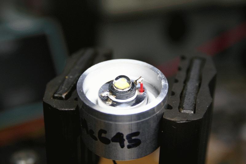
IMG_7285.JPG


ta-daaa:
IMG_7287.JPG


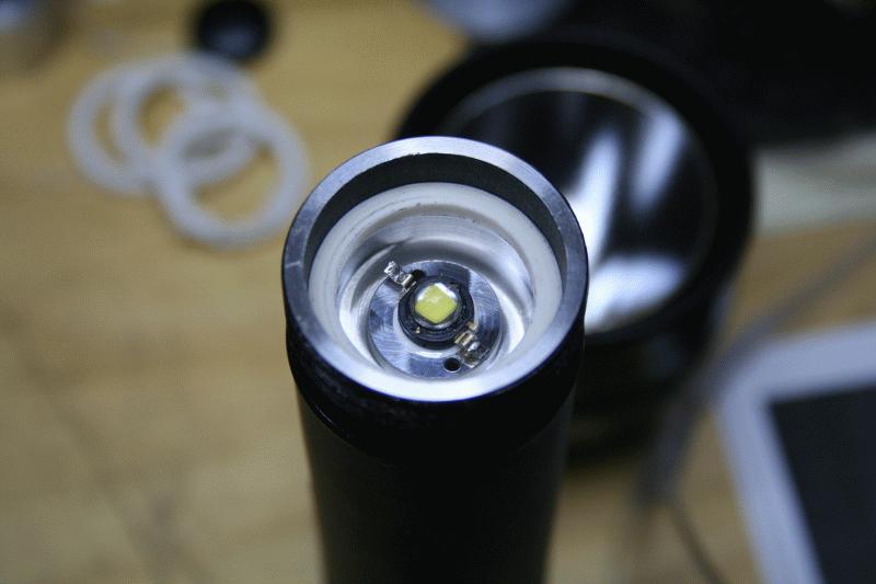
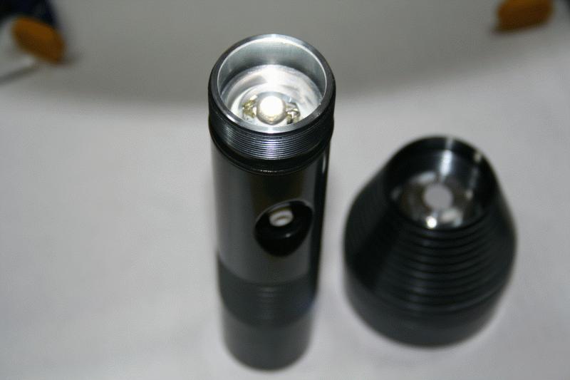
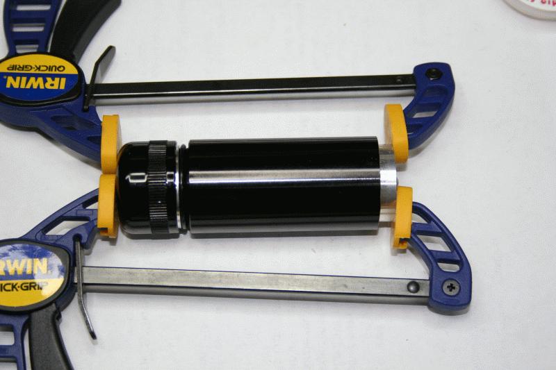
and a quick test using an actual 18650 cell, on its actual host (this LED was for the finned FM 1xC body):
IMG_7288.JPG


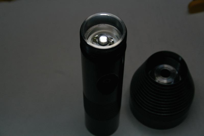
same photo with overhead light off to appretiate the LED being ON:
IMG_7289.JPG


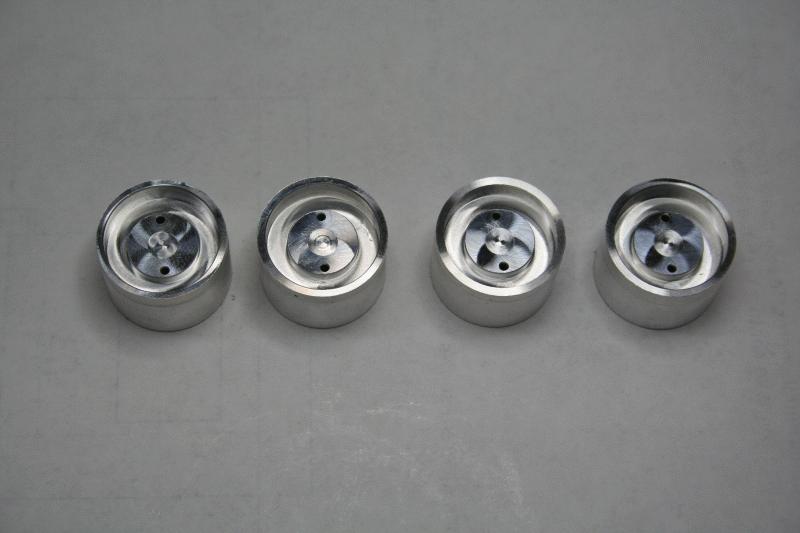
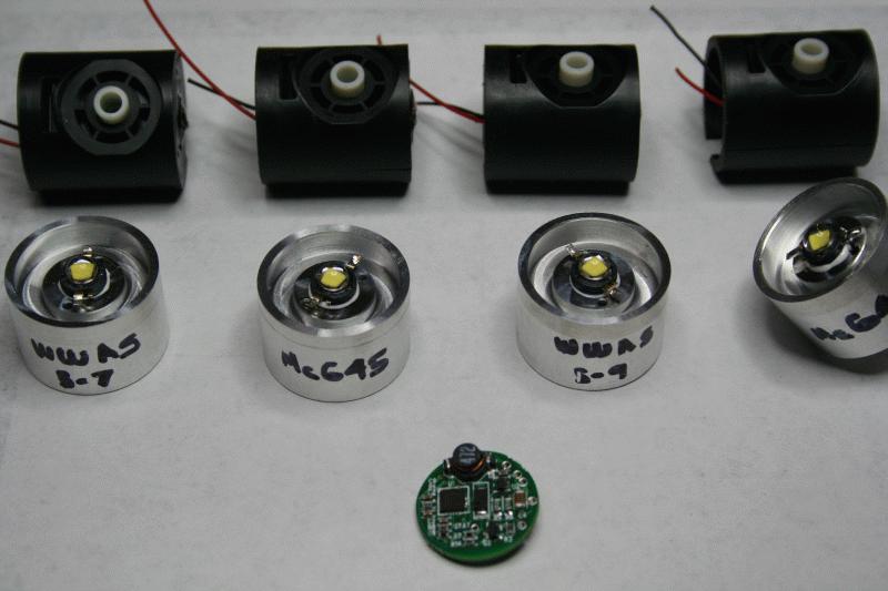
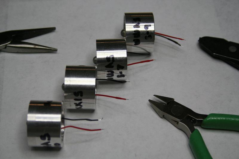
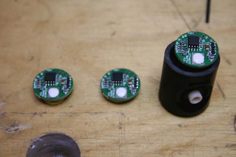
Then I did the other two 1xC HS/Driver combinations (leaving the 2xC for last due to being quite different):
IMG_7291.JPG


IMG_7292.JPG


IMG_7294.JPG


And that is all for today. More photos tomorrow ;)

Will
 
Top