• You must be a Supporting Member to participate in the Candle Power Forums Marketplace.

    You can become a Supporting Member.

Sold/Expired Custom McG45's for sale ...

wquiles

Flashaholic
Joined
Jan 10, 2005
Messages
8,459
Location
Texas, USA, Earth
cmacclel said:
Someone's busy :) Whats the AA on the MaxFlex Pad? Metal spring?
Its the same metal from the negative metal strip that goes up from the switch up to the bulb. I cut it in small pieces and used AA on both sides (one side at a time to let it stay in place).


ZeissOEM2 said:
Hi will.
Like I said earlier.
How bright can I get this without getting trouble .
The light works fantastic at the 1.0Amp I designed it for. It draws about 2Amps from the 18650 cell which is high but within the normal operating range for the 18650 cell. When I did an extended run at 1.0A on the prototype, the light gets warm, but never hot. I really recommend the 1.0Amp setting, and that is how I am shipping them, but you can manually change the current table to the 1.2A or 1.4A max setting via the same ON/OFF switch. I added a little bit of thermal protection as you can see in the photos above, so you can go somewhat higher, but longevity of the driver/LED will go down the hotter the light runs - its always a compromise ;)

Will
 

wquiles

Flashaholic
Joined
Jan 10, 2005
Messages
8,459
Location
Texas, USA, Earth
Thermal path from the converter to the HS. This is why I calculated the normal and worst case power usage for the McG45 lights which use the MaxFlex as shown above.

Here are the two sections in the MaxFlex' manual that talks about this:

**************************************************
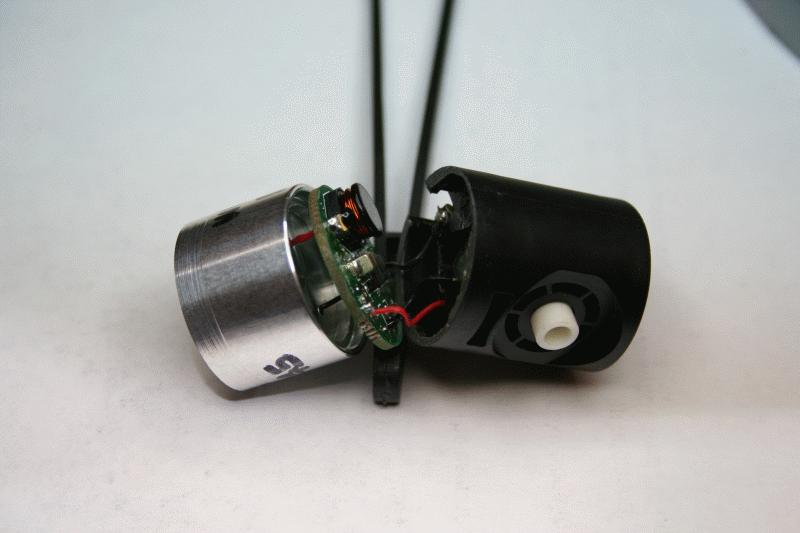
The exposed rectangular tinned area just above the (C) TaskLED is a direct thermal interface to the bottom of the switcher IC (on the other side of the PCB). If the power dissipation of the MaxFlex board exceeds about 1W it is recommended to affix a heatsink or copper tab to a heatsink to the exposed area. The exposed area is at Ground potential - i.e. electrically connected to the battery GND and LED- pads. This means it is safe to mount the tab to a heatsink that connects to the body of a flashlight, IF the body of the flashlight is the same as the Battery negative or ground.

**************************************************

Examples on how to calculate battery/LED combinations:
Step 1: Determine output power
Power_output = Number_of_LEDS * Vf * Output_current
Step 2: Determine input power
Power_input = Power_output/efficiency
For calculation purposes we can assume efficiency will be 85%
Step 3: Determine input current
Input_current = Power_input / Battery_voltage
Do this calculation for the lowest Battery_voltage you plan to run

Now, Input_current should be around 2.6A or less for optimal performance of MaxFlex. When running at high input power it is recommended to solder a tab to the pad on the back of the MaxFlex board (the pad is at ground potential) and to bolt it to a heatsink or the body of the flashlight.
**************************************************

Basically, this thermal path allows the converter to work optimaly, plus I am sure it will work longer this way as well. I am a double EE by education, so I took this warning/recommendation from George very seriously ;)

Will
 

cmacclel

Flashlight Enthusiast
Joined
Jul 15, 2003
Messages
5,018
Location
Sweden
Thanks.....but could'nt you have just of soldered the piece of Mag ground strap to the MaxFlex?

Mac
 

wquiles

Flashaholic
Joined
Jan 10, 2005
Messages
8,459
Location
Texas, USA, Earth
Yep, I just got an email from George late last night. I will definitely wait a little bit before sending the lights out until we know more from George.

Lets see what he can find out - all 3 of the MaxFlex drivers are pottet and glued :ohgeez:

Will
 

cmacclel

Flashlight Enthusiast
Joined
Jul 15, 2003
Messages
5,018
Location
Sweden
Icarus said:
Great pictures Will! :thumbsup:
Have you seen George's post on the problems with the MaxFlex?
I suppose your MaxFlex's are running fine? :thinking:


Man........ I left the computer right before your post Freddy! I just spent 3 hours playing with the MaxFlex. After I installed two with different issues I spoke with George and he informed me there was a bug.(nice guy BTW)


MAc
 

wquiles

Flashaholic
Joined
Jan 10, 2005
Messages
8,459
Location
Texas, USA, Earth
I will know myself in a few more hours when I go try assembly the first light tonight ...

I will report what I find out :candle:

Will
 

Icarus

Flashlight Enthusiast
Joined
Nov 1, 2003
Messages
3,495
Location
Belgium
I ran a Tri-LuxIII for more than 6 hours using the 700mA drive table without any problem. :thinking:
 
Last edited:

cmacclel

Flashlight Enthusiast
Joined
Jul 15, 2003
Messages
5,018
Location
Sweden
Icarus said:
I ran a Tri-LuxIII for more than 6 hours at the 700mA drive table without any problem. :thinking:

I ran my Tri-Lux "X" bin with no issues either, and I was pulling 2.6amps from the MaxFlex.

In the setup I was building this morning was a single "X" bin running from a 4AA NiMH pack. At 700ma and above the light would shut down if a few seconds when on high. Same thing with my next board but that one also would just flash like it was in strobe mode.

Mac
 

wquiles

Flashaholic
Joined
Jan 10, 2005
Messages
8,459
Location
Texas, USA, Earth
Well, my drivers "do" have the problem, at least at my drive levels. I am driving the 5W at 1A and pulling 2.0A @ 4.0V from my PS which is about right. But sure enough, the driver does excibit the problem at this drive level :(

Until further notice, these 3 lights using the MaxFlex are on hold until George can figure out what to do next. I ran out of time to work on the 2X (which uses the bFlex) due to debugging this problem, but I hope to work on it next weekend.

Sorry for the wait folks. I will try to keep you guys updated.

Will
 

MSaxatilus

Flashlight Enthusiast
Joined
Sep 24, 2002
Messages
2,641
Location
New Jersey
Thats fine with me Will. I'd rather have all the bugs worked out first!

Thanks for all the updates.

MSax
 

wquiles

Flashaholic
Joined
Jan 10, 2005
Messages
8,459
Location
Texas, USA, Earth
Thank you guys. No point sending you guys something flaky - I would never do that.

Even if we have to wait, the lights will be ready when they are working fine - no worries ;)

Will
 

wquiles

Flashaholic
Joined
Jan 10, 2005
Messages
8,459
Location
Texas, USA, Earth
Well Nebula, your light is ready. Since you got the 2xC, you are using the bFlex driver from George which is error free and a solid performer. The only drivers with the problem are the MaxiFlex which are used in the other 3 lights, all of which are 1XC. So you got "lucky" ;)

Your light took extra time to get fitted since the bFlex is physically larger than the MaxiFlex, and it took more modifications to the switch and the heatsink in order to fit:

Here is after the swich and heat sink were modified:
IMG_7330.JPG


here is right before epoxing everything together:
IMG_7333.JPG


here is the module waiting for the epoxy to dry:
IMG_7334.JPG


Here is your finished light (the piece of plastic underneat is to keep it from rolling):
IMG_7340.JPG


I tried to remove as much of the dust in the reflector and UCL lens, but I think you can still see some - good thing is that it does not affect the beam at all:
IMG_7341.JPG


and here is your light in action:
IMG_7335.JPG


Now, your light is finished, but right now I can't fit anything but 2 unprotected 18650 cells. Both brands/types of protected cells are just a hair too long and the tailcap will not close all of the way:
Unprotected cells:
IMG_7337.JPG


Protected cells brand1:
IMG_7338.JPG


Protected cells brand2:
IMG_7339.JPG


I could perhaps take some of the tickness of the inside of the tailcap with my lathe, but I am not sure I can take enough to make a difference. I don't know what to try.

The bFlex does have the low battery warning setpoint, which would be awesome with unprotected cells, but it is "your" custom light. What do you think? Are protected cells what you intented to use?

Will
 
Last edited:
Top