Energizer 15 minute charger cycle

Ray of Light:

Here's a scope screen capture a short time after the green LED came on but it only lasted a short time at 1.37A and dropped to about 70ma then zero. I waited till the charger's fan turned off which is several minutes and seen nothing! I mention in another thread that I didn't think that this charger had a trickle mode.

My cells come off the charger at 1.4V or so, maybe it's the cells?

These scope screen captures look pretty good! :D I could fit three across too!
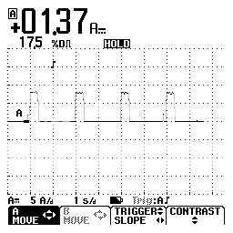
en_aa_scr_2.jpg
 
Last edited:
Ray of Light:

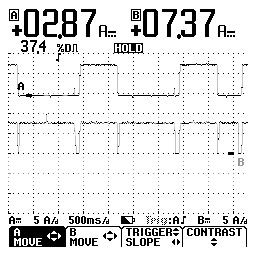
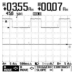
Here's a couple of scope screens with a AA and AAA connection at the same time. The first is both charging and the AA happen to finish so I grabbed that one too! I kept on getting a blinking red LED for various reasons, one was my connections and the other was that it didn't like the cell. Could be the state of charge or whatever. It seems to be very touchy about that.

en_aa_scr_5.jpg
en_aa_scr_4.jpg
 
Looks to me like it does charge different cells at the same time then. Which is nice...

From what people have said it does seem to be a bit picky about connections etc to get the flashing red lights. But I have yet to get this to happen so can't really comment.
 
the beast:

Well, remember that I had numerous connection points that could cause a problem! Four clips, four spacers, two clamps and all the wires in between too. It was some site. My workbench is some site too! :D
 
I thought that I'd keep this in the same thread but somebody asked about the termination on a Energizer 15. I tried different scope setting trying to spot -DeltaV but if it's anything at all, it's ZeroDeltaV.

en_aa_4.jpg
 
I was looking at the termination of the E-15 using Titanium 2Ah, Energizer 2.5Ah and Duracell 2.4Ah AA. I discovered something rather interesting!

After the LED turned green and the fan is still running the E-15 is still charging at a reduced rate using PWM current. After exiting the TrendPlot mode of my scope, I'd see those pulses mentioned. I got a blinking LED on one of the Energizer 2.5Ah cells do to a bad connection, rotated the cell in my clamp and away it went. When the LED turned green there were no pulses at all. I thought at first that it was do to the error and maybe the unit should be RESET by unpluging the unit. I was wondering how the next cell would do. The following two cells pulsed at the end, normally.

I got to the Duracell 2.4Ah cells. The first three didn't pulse but the last one did! All the Titanium 2Ah did.

So there is something going on here with this E-15 and certain capacity or brands of cells. This would cause a undercharged cell and I assuming no trickle after the fan turns off either.

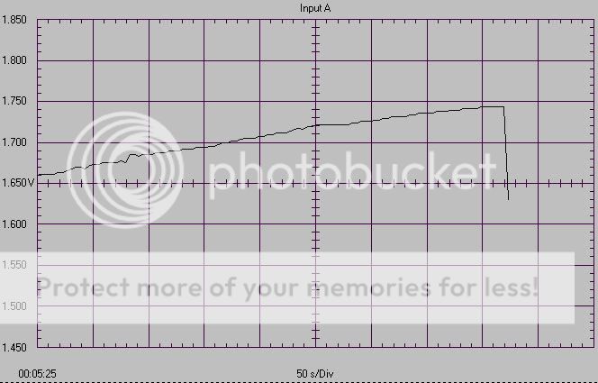
I post some graphs later but the E-15 uses ZeroDeltaV for termination, no doubts now.
 
Last edited:
Hi there,

Just a note...

With your measurement scale setting you wouldnt be able to see the
minus delta V if it was in fact present, because it is only 10mv in most
cases. You'll need to home in on the graph by using a more sensitive
setting or something, if that is possible.
 
MrAl said:
Hi there,

Just a note...

With your measurement scale setting you wouldnt be able to see the
minus delta V if it was in fact present, because it is only 10mv in most
cases. You'll need to home in on the graph by using a more sensitive
setting or something, if that is possible.
Well, if I zoomed in and used the cursor values, it would be more visible. I should replace/delete that last graph that I posted.

In new graphs with a finer timebase, ZeroDeltaV termination is clearly seen. The odd thing is the point that some cells cause the E-15 to not complete the cycle. I seen this more with Duracells than other brands. Worse than that is while testing some Duracell 2.3Ah cells, the E-15 missed ZeroDelat termination went through -DeltaV termination and proceeded to cook the cell to over 140F even with a small fan blowing on my externally connected setup! A cell or two triggered a blinking LED but charged in the unit itself but two more seemed to miss termination also even while charging in the unit! Luckily, I was monitoring temperature with a IR probe and pulled the plug.

I'm confused by this! I'm going to check the unit out with other cells, etc. These are the same batch of Duracell 2.3Ah that melted my BC900!! I wonder.....

EDIT: Rejected cells from the E15 charge fine on D15(Duracell 15 minute charger).
 
Last edited:
Hi again Bill,

Hey that's very interesting, and here is why...

I too have some Duracell cells rated 2050mAh, and these cells remain
warm in the charger (not hot though) even after the LED turns green.
None of the other cells do this (Energizer 2200, RS 1800), only
the Duracell brand.
The only other brand i have tested so far is the "Digital" brand cells,
which the charger wont accept (blinks LED red).

Im not sure if i am happy with the charger or not, but i guess i am.
I could be happier though, if it charged at 10 amps or at 7amp while
letting the cells charge a bit longer (20 mins or so).
I guess this is one of those devices where i am going to have to try it
out over a period of months to get an idea how much i really like or
dislike it. Some day i'll get a set of eneloops to try in it too.
 
Al:

I was getting a blinking LED with every Duracell 2.3Ah that I tried! I wasn't disconnecting the battery clamp from the charger nor the voltage test leads either. I happened to notice the voltage reading on my scope, it read way over 2.0V. I then disconnected the battery clamp when inserting a cell, no more blinking LED and a few more that I tested showed a complete cycle. That was causing "some" of the funny stuff that I was seeing. Not sure if that caused it to miss termination but it hasn't happened since changing my procedure.

I to have some Energizer 2.2Ah cells which I tested and will post a post some graphs. I promise again! :D I'll have a few Titanium 2Ah tomorrow that I'd like to look at again, then I'll be able to post graphs.
 
Hi again,

You know, if your charger switches to 3.5 amps then it must mean it
thinks it has an AAA cell in there instead of an AA cell.
Not sure yet how this charger detects AA and AAA cells.
 
MrAl said:
Hi again,

You know, if your charger switches to 3.5 amps then it must mean it
thinks it has an AAA cell in there instead of an AA cell.
Not sure yet how this charger detects AA and AAA cells.
It shouldn't. Somewhere above it's discussed how I made that mistake! It detects by how much the spring loaded positive contact is depressed. It makes the AA positive at almost fully depressed position too.

I used use one 1/4"x 1" magnet and a piece of 1/4" drillrod with a chamfred edge to fit inside the recessed positive contact. I use insulator between the two which fits tightly in the E15 and clip to the spacers.
 
Hello again Bill,

Oh ok i see now. So it uses a mechanical means to determine which
cell is in there...well then i have no explanation of why yours thinks there
is an AAA cell in there, or alternately, why it thinks it should be charging at
the AAA cell rate. Makes no sense now. Guesses, guesses, and more
guesses at this point ha ha. Time to start making some solid measurements.
Thanks for reporting all your finds too and measurements too. At least
now i have some idea how this thing works and what to look for when i
start my own measurements.

OH yeah BTW, i had read that you are not supposed to charge
different types of cells at the same time. This is probably because
they are done in series and you can satisfy all the cells current
requirements when they are different and they are all in series.
Did you by any chance have different cells in there at that point
where it went down to 3.5 amps?
 
Last edited:
Al:

Nope the was with only one cell connected for the tests. I tested twice as much Titanium 2Ah cells and only one cell skipped the 3.5A part of the cycle.

Look at post #22 above, lefthand screen. That's a AA and AAA connection at the same time with two different charging rates. Then again if you have one or more of the same type, AA or AAA cells in different state of charge. Some finish before others. Or does it wait for others to reach each stage? I can test with two connections but if I did with a AA and AAA connection above, what does that prove? My head hurts! :D

Gee what thread am I in? I'm going to post some shots in one of these threads of Duracell 2.65Ah, only one did the 3.5A part of the cycle.
 
Hello again,

Ok, so i guess what happens if you put in AA and AAA at the same time
is the thing pulse width modulates the current into the AAA cells so its
average is reduced. No problem with that.
What is interesting is that the 'manual' (that tiny bit of paper that comes
with the charger ha ha) says not to charge cells of different capacities,
but that doesnt make sense either since the lower capacity cells would
simply shut off sooner. Not only that, but AA and AAA are not the same
capacity ha ha.
 
Al:

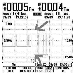
Here's another scope screen of two MAHA 1.8Ah AA cells that I made sure one was more discharged than the other, so one would finish first. Both reading current but the second trace has some garbage in it which happens everytime the reading goes OL. Not sure why it does although I have read posts in other forums asking why they do this! I used my other two probes for this test so the current reads a bit higher.

I've pointed to a period in time at which each cell is receiving two different rates of current. These cells are in series, how does it do this? Switching alternating PWM? :thinking: This is only two cells, what about four at different states of charge??

Notice that these MAHA 1.8Ah cells also do the 3.5A part of the cycle too.

EDIT: I just setup a test to monitor the current at the point shown below but not in graph mode as to see the PWM. I was looking to see a alternating pulse or while one cell is ON the other is OFF. Not only did I not see that but there was no difference in the pulse width at that time! So how come I'm seeing twice the current on one cell?? This is with two different current clamp probes and also a current clamp meter too. They all can't be wrong! Am I confused now!! :ohgeez:

mh_aa_cc_1.jpg
 
Last edited:
Hi there,

The only explanation is that they are using PWM to control the current
to *each* cell. This would be possible by switching each cell in and out
rapidly relative to the time base of your measurements. On a faster scope
you should see pulses, unless of course they also use small inductors to
smooth out the current to each cell. Perhaps you can decrease the
time base to see if you can spot some narrow pulses.

Keep in mind i dont have a schematic in front of me either...im guessing
as we go based on the measurements you and i have made.
I had determined 'series' charging because of the high voltage seen on
some of the cells relative to others, and also because as i peek into
the slots of the charger i can only see one inductor. Maybe take it apart
and examine the guts more closely?

We also have to keep in mind there is a PIC-like controller in there.

LATER:
Again verified the series configuration by measuring the voltage
at the (+) terminal of each cell during charge, relative to the
(-) terminal of the cell in the far right bay. The voltage of
the first cell is about 1.7 or so, the second is double that,
the third cell is triple that, and the last cell is about 4 times
that. Also, measuring between any two cells is about 3.4 or
so volts, and between any three cells is about three times 1.7
volts.
I also noticed that after the led lights green the charger pulses
all the cells as if it is testing them. The pulse is low duty cycle
as the voltage jumps up, then down. This also proves the
cells are being disconnected from each other when they are
done being charged...the voltage across all the cells jumps up
to 7.5 or something, then down to what looks like zero
(but the analog meter doesnt get time to fully rest).
 
Last edited:
Al:

I'm thinking that the switching is just too fast for my scope to see! I'll fool with more as I get more discharged cell to try. That's the bottleneck, either I make cells to test or wait for cells in use to come around. Hate to waste cycles you know!

I too verified the series connection of the cells.

In reference to the screen in post #22 again. It shows a different duty cycle on each cell at the same time but the confusing part is why I didn't see that with two AA cells. Unless it's because it was a AAA and AA, two different modes or circuits.

I think that the pulses your seeing are what I mentioned too, very short at 4ms if I remember correctly.
 
Hi again Bill,

Yes, i well saying that the pulses might be too high in frequency to
detect unless you have a fast scope setting.

For quick testing you can let the cells stand overnight then charge
again the next day. They charge for a minute or less this way
so you have to make your measurements quick.

Thanks for verifying that series connection too.

I would think that not all of the cells (even all four AA) would finish at
the same time, so the input current to the charger would drop
in increments as each cell is completed. You can check this out by
putting your current clamp on the input side of the charger and have
four cells of same type in the charger.

The other pulses i am seeing look like 'feeler' pulses, which are used
to make measurements on the cells to see which ones are ok to
charge and which ones are not, or perhaps to detect end of charge.
The PWM pulses i am thinking might be on the order of 10kHz to 100kHz
pulses, too fast for the scope to see so they look like an average.
I could dig my scope out i guess and take a look...it will catch up to
maybe 20MHz pulses.
On a 'normal' scope the fast pulses would look like a bunch of hairs
across the screen. On a slow scope they might average out looking like
a dc signal whos level is determined by the duty cycle of the pulses
and partly by the reponse of the scope.
 
Al:

In order to look at the point in the cycle where one is at 7A and the other at 3.5A, I need the brand/capacity that do this. Not all do! Cells that are 2Ah or less do but higher than that, more don't than do. On top of that, you only have a few minutes to diddle with scope settings.

Even if cells used skip the 3.5A part of the cycle, one cell could still be charging and others down to the trickle charge. If you adjust the timebase to see one, you'll never see the other. I should be able to see the full 7A pulse along with those feeler pulses as you call them.

My scope is only 20mHz too, a Fluke 123 ScopeMeter. I do have two others meant for automotive work. Not sure if they'd be any faster though. One's a two channel and the other a four channel which might be faster than 20mHz. I can't connect the four channel to a PC! :(
 
Top