Steve K
Flashlight Enthusiast
hi gang,
One of my bikes was still equipped with a headlight that I built around 2000... using a Luxeon V LED! It was great for its time, but it is awful by today's standards. I needed to build a new headlight before winter set in, so I decided on just running two LEDs in series and adding a standlight circuit that I have used before...
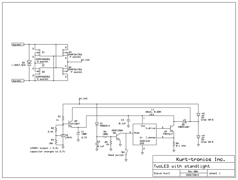
It does use a mosfet bridge rectifier, which I like because it helps maintain the light output when I slowly climb a nearby 14% grade.
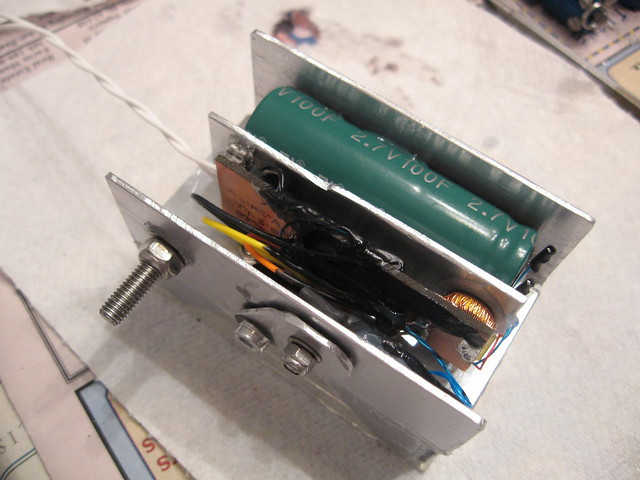
The standlight is powered by a 100F, 2.7V supercap. This is a change from my usual practice of using a AA nicad cell. I liked the idea that it won't require replacement after 10 years like my earlier headlight.
I considered just letting the standlight be active at all times, but I wasn't sure I wanted it to be running while it was parked in a bike rack. With a nicad, I always used a switch to disable the boost converter in the standlight. This time, I decided to try a reed switch for that purpose. The reed switch would be sealed up inside the housing, so it wouldn't become corroded or clogged with dirt.
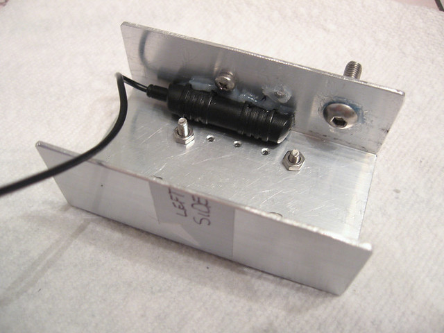
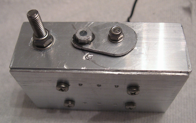
How to mount a magnet to activate the reed switch?? I sketched out a few ideas, but ended up with the concept of something that looks almost like a rotary switch. The magnet is housed at the end. I did use steel M3 screws to hold the magnet at the "on" and "off" positions, and the steel M3 also serves as a flux path between the magnet and the reed switch.
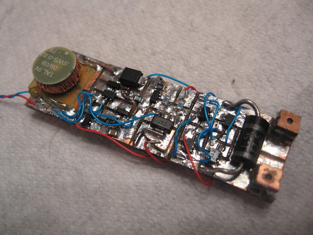
The circuit board was just hacked out of copper-clad circuit board. Not good looking, so I hide it inside the light (after coating it with plasti-dip).
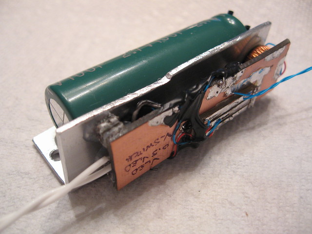
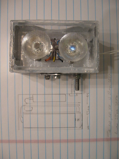
Getting everything mounted compactly and securely inside the housing, while allowing all of the wires to be connected can be a challenge. I sketched it out beforehand, especially with the size of the supercap in mind. It is pretty large and largely dictated the light's dimensions. I ended up making a subassembly of the supercap and circuit board. The was then connected to the LED wires and reed switch wires, and dropped into the housing.
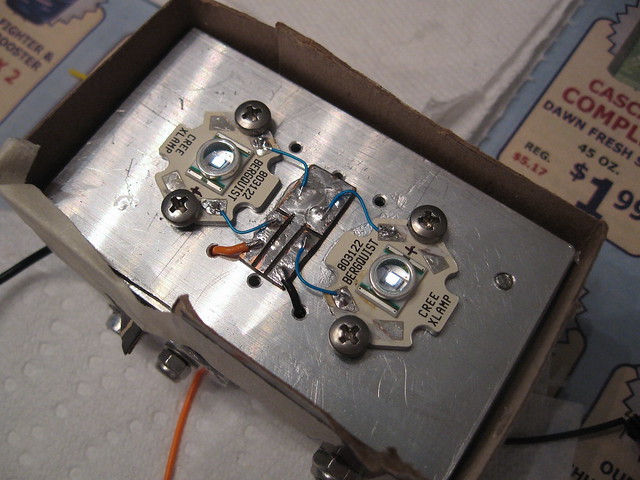
The LEDs are Cree XR-E's, which isn't what I started with. My first choice was XP-E2 LEDs, but I was having trouble with the Ledil Heidi optics, so I went to the fallback option of the XR-E with Ledil Rocket SS optics.
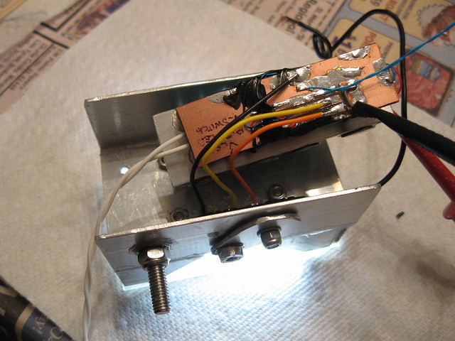
Once those wires were in place, I could hook the wiring up to the board and confirm that everything still worked....
With that accomplished, the final installation of the parts could take place.
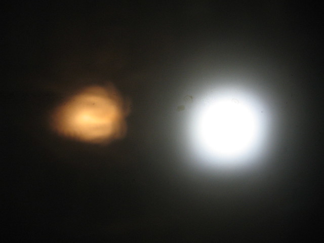
One detail that I hadn't figured out, or appreciated, what how much light could be produced when the supercap was connected through the disabled boost converter. With the standlight turned off, the current from the supercap can flow through a schottky diode to the lower LED. I figured this wouldn't happen since the LED had a Vf of 3.2v or so, and the schottky diode has a Vf of 0.2V or more. Well, I forgot that the LED would still conduct a small amount at 2.7v. In truth, it conducts a little even down to 2.3V. I'm not happy about it, but it's not a big deal.
Here's a shot of it when the supercap is close to 2.3V...
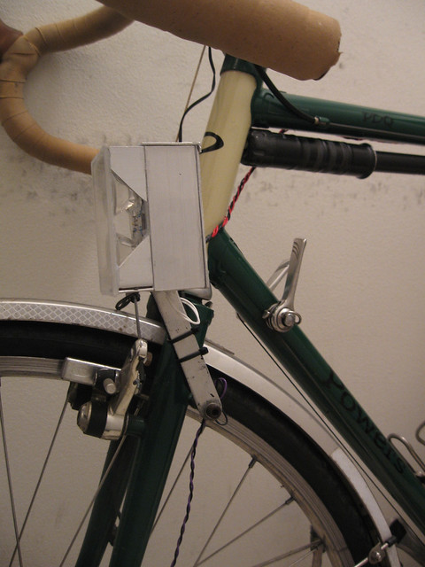
The light is finally done and mounted on the bike!!")
For something build out of aluminum extrusions purchased from the hardware store, I think it looks pretty good. At least it looks better than the light it replaces.
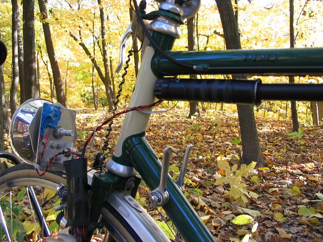
This is the light it replaces.. this light does look better from the front, though. The blue goop is covering a small circuit board with a mosfet bridge rectifier. Amazingly, it survived at least a decade of use like this, in all sorts of weather. The blue goop is Plasti-dip, which is normally used to coat the handles of tools. It does a tolerable job of protecting circuits from the environment.
Well, that's all for now! Time to ponder what the next project should be.
One of my bikes was still equipped with a headlight that I built around 2000... using a Luxeon V LED! It was great for its time, but it is awful by today's standards. I needed to build a new headlight before winter set in, so I decided on just running two LEDs in series and adding a standlight circuit that I have used before...
It does use a mosfet bridge rectifier, which I like because it helps maintain the light output when I slowly climb a nearby 14% grade.
The standlight is powered by a 100F, 2.7V supercap. This is a change from my usual practice of using a AA nicad cell. I liked the idea that it won't require replacement after 10 years like my earlier headlight.
I considered just letting the standlight be active at all times, but I wasn't sure I wanted it to be running while it was parked in a bike rack. With a nicad, I always used a switch to disable the boost converter in the standlight. This time, I decided to try a reed switch for that purpose. The reed switch would be sealed up inside the housing, so it wouldn't become corroded or clogged with dirt.
How to mount a magnet to activate the reed switch?? I sketched out a few ideas, but ended up with the concept of something that looks almost like a rotary switch. The magnet is housed at the end. I did use steel M3 screws to hold the magnet at the "on" and "off" positions, and the steel M3 also serves as a flux path between the magnet and the reed switch.
The circuit board was just hacked out of copper-clad circuit board. Not good looking, so I hide it inside the light (after coating it with plasti-dip).
Getting everything mounted compactly and securely inside the housing, while allowing all of the wires to be connected can be a challenge. I sketched it out beforehand, especially with the size of the supercap in mind. It is pretty large and largely dictated the light's dimensions. I ended up making a subassembly of the supercap and circuit board. The was then connected to the LED wires and reed switch wires, and dropped into the housing.
The LEDs are Cree XR-E's, which isn't what I started with. My first choice was XP-E2 LEDs, but I was having trouble with the Ledil Heidi optics, so I went to the fallback option of the XR-E with Ledil Rocket SS optics.
Once those wires were in place, I could hook the wiring up to the board and confirm that everything still worked....
With that accomplished, the final installation of the parts could take place.
One detail that I hadn't figured out, or appreciated, what how much light could be produced when the supercap was connected through the disabled boost converter. With the standlight turned off, the current from the supercap can flow through a schottky diode to the lower LED. I figured this wouldn't happen since the LED had a Vf of 3.2v or so, and the schottky diode has a Vf of 0.2V or more. Well, I forgot that the LED would still conduct a small amount at 2.7v. In truth, it conducts a little even down to 2.3V. I'm not happy about it, but it's not a big deal.
Here's a shot of it when the supercap is close to 2.3V...
The light is finally done and mounted on the bike!!
For something build out of aluminum extrusions purchased from the hardware store, I think it looks pretty good. At least it looks better than the light it replaces.
This is the light it replaces.. this light does look better from the front, though. The blue goop is covering a small circuit board with a mosfet bridge rectifier. Amazingly, it survived at least a decade of use like this, in all sorts of weather. The blue goop is Plasti-dip, which is normally used to coat the handles of tools. It does a tolerable job of protecting circuits from the environment.
Well, that's all for now! Time to ponder what the next project should be.
Last edited: