I also heard that led's need a resistor, now do i need a resistor for it or would there be one on the sample led coming? Also what is the driver? is it the pcb? And what battery would i need?
There will NOT be a resistor on the LED sample.
The rest of your question is both huge and very important to being able to control the light output, LED lifetime, and battery burn time. A thorough explaination is not going to be achieved in a single post, or even in several, so I won't even attempt it. But maybe I can simplify it enough to be helpful.
In a very simple view, a battery can be considered to be a voltage source. Ideally, it will give you any amount of current at a fixed voltage until it is fully discharged.
But of course no battery really does that. The more current you draw, the lower the voltage is. The voltage also drops as the battery discharges. A fully charged Lithium cell is 4.1-4.2V, and you can discharge it to 3.5, 3.2, 2.7, 2.5V, or even lower. The more deeply you discharge it the more energy you get per charge, but the fewer charges the battery will last.
In a very simple view, the LED can be considered to be a fixed voltage load. Ideally, it will absorb any amount of current at a fixed voltage. By the way, the amount of current through the LED is the primary factor in how much light it puts out.
So if you connect a voltage source to a voltage load, what happens? If the source voltage is higher than the load voltage, an infinite current will flow. Clearly this can't happen. A college professor of mine used to say that this would cause an 'anihilation wave' to propogate from the event at the speed of light. Not something I relish experiencing. If the source voltage is less then the load voltage, no current flows. This is pretty boring, as it looks a lot like unconnected parts laying on the bench. If the voltage source and voltage load are exactly the same, the current could be anything from boring to anihilation. I want something more reliable.
So what do we do? This is where the driver comes in. The driver's job is to control the current in the LED when the battery and LED voltages don't match.
A resistor is a really crude form of driver. If you wire battery, resistor, and LED into a loop (and get the polarity correct), the current in the loop will be determined by the Battery voltage, LED voltage, and resistor value according to the following equation:
Current = (battery voltage - LED voltage) / resistance
You can see from this that as the battery voltage changes, the current will change, which means the light output will change. It will start dropping as soon as you turn on the light and continue dropping until you turn it off.
A better driver would be a variable resistor, that automatically adjusts to keep the current the same no matter what the voltages do. A linear driver is essentially this.
Even better (in most cases) is a switching driver. If the voltages are much different (like 3.4V LED and 6-8V battery), a resistor or linear driver is very inefficient. A good swtitcher can handle the voltage difference, regulate the current, and maintain high efficiency.
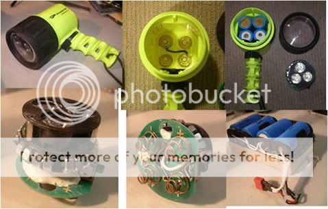
I am also going to need some help on the reflector a swell. Would the current one suffice? ( i can upload a photo of it if need be)
The current reflector will work poorly with an LED, even after you to modify it. The reason for this is that it was designed to catch light coming out the bulb sideways, backward, and slightly forward, and focus that into the 'spot'. Light that comes out more forward will not hit the reflector, and will spread wide to form the 'spill'. An LED has mostly 'more forward' light, so only a little will hit the reflector and form a very weak spot.
For an LED you need a much deeper, narrower reflector, or a lens of some sort.