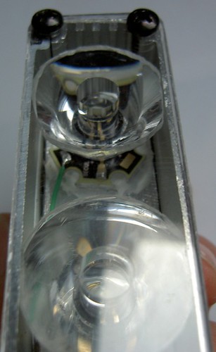
Let's design a road front light beam

sfCyclotourist

Newly Enlightened
Joined
Nov 30, 2006
Messages
93
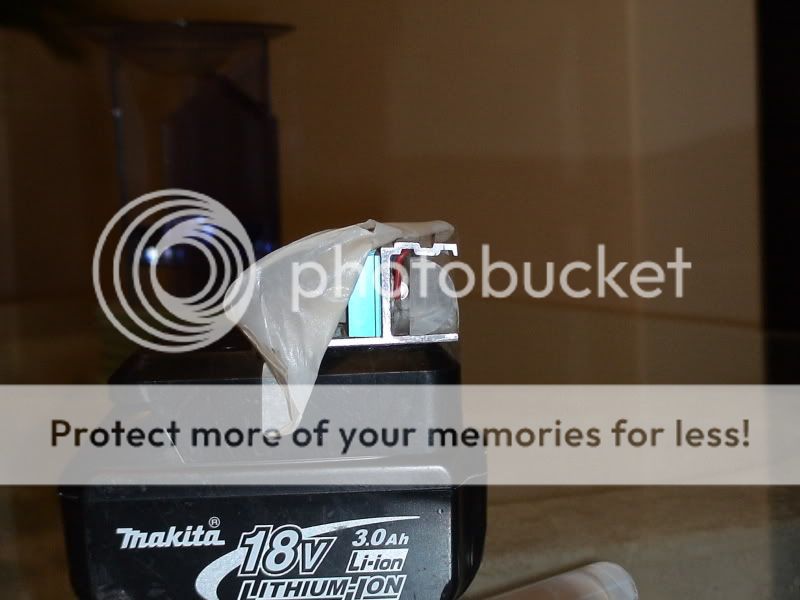
I came across a DIY light in a square aluminum conduit/pipe that had the LEDs and optics recessed in the conduit, and a front of the conduit bias cut so that the top edge extended further than the bottom edge.

I remember that the builder said it provided a trapezoidal beam pattern, but I had not bookmarked it at the time, and can't seem to find it anymore.

GOOD GOD I remember that too, didn't bookmark it, and now can't find it either. At the time I thought it was brilliant. The one missing detail is that the builder just used a bare LED in the square tube, there was no lens or optic. The result was a nice square beam, although there wasn't much of a brightness gradient to it, if I recall correctly.

It seems that you could try doing this and also have the LED and optics offset so that it points slightly upward within it's recess, causing the hotspot to be closer to the top edge of beam pattern, and spilling more light downward right in front of the light, lighting up the region right in front of your wheel better.

See also http://www.enhydralutris.de/Fahrrad/LEDWerfer0402/index.html

You could probably prototype this with just some conduit, a hacksaw and an existing flashlight. I just tried it with a sheet of aluminum and a flashlight to see how it effected the beam and after you adjust for the beam angle, it seems to do a reasonable job of causing a sharp cut off of a bright top edge, and reflecting the light down in front of the light. But it only works if the LED beamline and the top "hood" aren't parallel. The hood has angle into the beamline. In a way, you could claim that its an improvement on the B+M design, because you don't have a dark area right in front of the bike anymore.

FWIW, very early car headlamps used an "eyelid" over the upper part of the headlight lens to (presumably) do something similar. I've thought of cutting up some old CD-Rs, using the shiny side as a mirror to cut off the top part of a headlight's beam, but I haven't fooled around much with this idea yet...
 

sfCyclotourist

Newly Enlightened
Joined
Nov 30, 2006
Messages
93
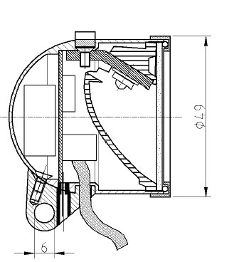
Edelux cross-section:
The axial cross-section looks like a straight parabolic reflector. The lateral section is more complex, given the beam shape.
3079937459_270bb5a758.jpg

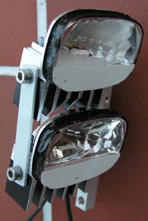
I've thought about trying to source some VERY cheap auto driving lights, to try to use their reflectors/housings to duplicate something like this:

p9161050_s.jpg


(from http://www.enhydralutris.de/Fahrrad/LEDWerfer0402/index.html)


Only complaint with edelux, now that I've had it a few days is that it is a very small patch of bright light. With the Dinotte it works fine, but it would be marginal at speeds.
I've read a few reports where people state that they prefer the E3 over the Edelux because there's more side spill. The E3 is also available with a StVZO-style focused optic, although that version is not StVZO-legal because it too still has too much spill. HOWEVER that might be the best compromise because it sounds like you wouldn't need an auxiliary light to read overhead signs, etc.
 

syc

Newly Enlightened
Joined
Jun 10, 2008
Messages
155
So, if you *really* want that kind of tight beam, several threads provide the details necessary to get pretty close.

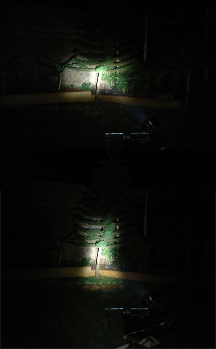
With a DX aspherical lens that provides a tight, low spill beam pattern. See this thread for the original discussion.

Beam on the wall:
lens-test2009.jpg


Outdoors:
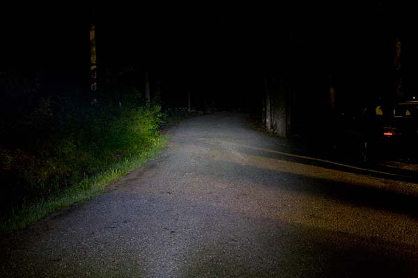
MCEBEAMSHOTS-ONTRAIL010.jpg


Or, if you want a really science-fiction style beam pattern, focus the aspheric optic better and get this:

lens-test2010.jpg


On the trail:
MCEBEAMSHOTS-ONTRAIL011.jpg


(Use that beam pattern out in the Marin boonies at night, and the dairy farmers will think aliens have come to abduct their cattle)

And per znomit's message, you can wire up the MC-E dies so that you get high current through the top pair of dies, and half the current through the lower pair, getting you brighter intensity in the upper half of the beam:
2s2pb.jpg


This would get you a square beam with sharp cutoff, and higher intensity on the portion of the beam that is further out. Power requirements would be comparable to a triple LED setup, which might still generate usable light around 6-7 mph on the most recent binned LEDs on a simple rectifier circuit. Using Martin's circuits, you could get up to 5.2W of lighting with a hub dynamo.

It would be tempting to drop one more LED in with the MC-E with an elliptical optic angled downward from the MC-E beam to get a nearby, broad beam as well (and put a standlight cap on it), so that you get the power draw of 4 LED's, but you just use Martin's Circuit 10 on low power (half the wattage) most of the time, and kick in it up to high for fast descents where gravity will give you the extra watts. If you used Martin's autoswitching circuit, maybe you'd have your DIY Edelux triple (more like a Edelux quad - though aspherics seem to have more light loss, so perhaps still only like a triple).

Another option that I thought about would be to get an elliptical diffuser, and only apply horizonal diffusion to the lower half of the MCE beam (without lowering the current to them), which would give you the sharp cutoff, and a top edge of the beam that travels far down the road, while also a broad beam nearby. You'd have to get some of the elliptical diffusion film or else hack up one of the L2 beam shapers. In some ways, this might actually be the simplest, cleanest solution.

Eventually I'll get around to trying this, but I need to finish up my current MCE light before picking up more LED's for projects.
 
Last edited:

Boco

Newly Enlightened
Joined
Oct 23, 2007
Messages
5
Attempted translation

Translation of German bike light regulations
• HV mindestens 10 lx
In HV soll die max. Beleuchtungsstärke liegen. Befindet sich die max.
Beleuchtungsstärke seitlich von HV, so darf deren Wert das 1,2 fache
des Wertes in HV nicht übersteigen.

(at HV in the diagram, minimum 10 lux, the maximum brightness should be around the point HV, if the brightness is to the side of HV it can't be more than 1.2 times the value at HV)

• Von HV aus 4° nach beiden Seiten bis einschliesslich zum Punkt L1 bzw. R1 sowie 1,5° unter HV bis einschliesslich zum Punkt 2 mindestens die Hälfte der
Beleuchtungsstärke in HV.


(from HV out 4 degrees on either side up to an including point L1 and R1 as well as 1.5 degrees under HV up to and including point 2 the brightness should be at minimum half the value of brightness at HV)

• Bis 5° unter HV, zwischen Punkt 2 und einschliesslich Punkt 3, mindestens 1,5 lx und von dort nach links und rechts bis einschliesslich zu den Punkten
L4 bzw. R4 mindestens 1lx.


(from 5 degree under HV, between points 2 and 3, there should be a minimum of 1.5 lux. From there to the left and right out to points L4 and R4 there should be a minimum of 1 lux.)

• In der Horizontalen 3,4° über HV und darüber hinaus (Zone 1) höchstens 2 lx zulässig


In the horizontal 3.4 degrees over HV and above (Zone 1) highest brightness allowed is 2 lux.

my best shot,

Dave
 

hit4six

Newly Enlightened
Joined
Jan 26, 2009
Messages
87
My perfect headlight -each led would have its own optics or projector style lens (asherical). 1/3 of its output is spread evenly where an automotive low beam is spread. 1/3 is narrower, along the middle of this low beam. And 1/3 if projected at a very tight angle so that it lights up the road a little further ahead than a car low beams. Shone against a wall, the intensity would increase from bottom to top but there would be no spill above the cut-off due to the use of aspherical lenses. And it would be mounted at the bottom of the fork or half way up the fork. CCT around 3200k.

I just found this great forum post that describes how high/low beams work in US and UK auto headlamps: http://www.isfanatics.com/forums/sho...d.php?p=418221
whoever copied who, it looks like that site had better information than wikipedia.

(EDIT)

Great thread (for me at least). I'd come across it before but I should have spent more time digesting it. A lot of ideas. And how I WISH this site was more 'TRANSPORTATION lighting - bicycle' than 'SPORTS EQUIPMENT -off road mountain bike lights.' Off road lighting seems much less difficult.

I don't see any reason to mount the headlight anywhere near the handlebars. Lower down throws longer shadows which means it easier to see potholes, bumps, rocks, glass, and the types of things that I'm trying to avoid.
I had a lot of misery before I worked that out for myself and I still don't think I've seen a bike with low mounted lights other than my own. (~8 degree, 38 degree)
 
Last edited:

sfCyclotourist

Newly Enlightened
Joined
Nov 30, 2006
Messages
93
From my own experimentation, what looks most promising would be a light with separately-aimed emitters for high beam and low/dipped beam, and for the low beam to have a wide beam pattern that helps the rider see peripheral reference points (such as the fog line and center line of the road, guardrails, etc) so he/she doesn't easily become disoriented in the face of oncoming lights.

Well, you could build this

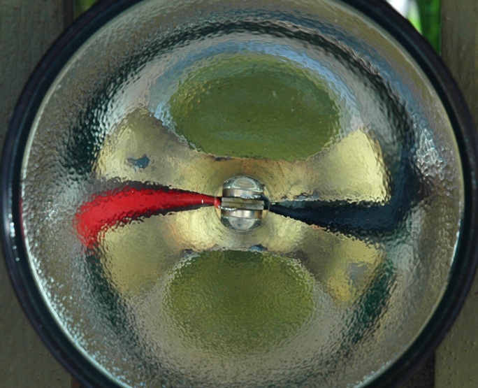
O-U-Reflector.jpg


Which gives a bow-tie beam pattern like this

O-U-Vert-Horiz.jpg


If you orient the beam vertically, and then add a switch to one of the LEDs, that should give you a low beam with cutoff, and a switched high beam.

This beam isn't trapezoidal like true ECE beams, but it's pretty close in function. Seems like it'd be pretty easy to build, too.

-Jim G
 

syc

Newly Enlightened
Joined
Jun 10, 2008
Messages
155
Surplus shed has a couple of aspherics with (apparently) the right characteristics for a bicycle headlamp: A 12mm diameter lens with 6mm focal length and a 39mm diameter lens with 20mm focal length. If the emitter dies are at the focal point, the lenses will cover a 90 degree cone that ought to capture most of the light from a XRE. And if you brought it in some more to defocus it, it could grab even more of the light. It will be interesting to see how well it works with an MC-E and try the wiring patterns that znomit suggested. The difference in brightness should be a lot more apparent with the aspheric than with the other optics.

This rectangular lens might actually provide a useful beam pattern. But I have too much stuff to play with already.

I have the aspherics on order and will post some results after they arrive and I can test them.
 

hit4six

Newly Enlightened
Joined
Jan 26, 2009
Messages
87
Surplus shed has a couple of aspherics with (apparently) the right characteristics for a bicycle headlamp: A 12mm diameter lens with 6mm focal length and a 39mm diameter lens with 20mm focal length. If the emitter dies are at the focal point, the lenses will cover a 90 degree cone that ought to capture most of the light from a XRE. And if you brought it in some more to defocus it, it could grab even more of the light. It will be interesting to see how well it works with an MC-E and try the wiring patterns that znomit suggested. The difference in brightness should be a lot more apparent with the aspheric than with the other optics.

This rectangular lens might actually provide a useful beam pattern. But I have too much stuff to play with already.

I have the aspherics on order and will post some results after they arrive and I can test them.
Can't wait to see ! It would be a bit ambitious for a first led build so I'll wait and see what you come up with. I still think multiple single die emmiters with differing optics would be ideal. I saw this thread https://www.candlepowerforums.com/threads/225519 comparing various emitters against a wall.

A word on brightness (sorry if that is a tired old topic). I don't know what other riders require (depends on bike, road, street lighting, riders eyesight(!) speed, weather conditions, familiarity with route), but I would not be interested in going less than my current Mr16 halogen setup. I estimate I have 700+ lumens each lamp ('20w' philips masterline or osram Irc run at 15v) and I have capacity to run three lamps if I'm willing to buy and then carry extra batteries. One lamp already looks ridiculously bright on dry, lighter coloured road surfaces, but on damp black tarmac I would not be comfortable with less light, and for rain I want more. And I've so far avoided mentioning colour rendition, I think I'll have to see an led that performs to my liking on tarmac before I'm converted. I reckon low mounting is more important than CRI.

A P7 torch, a lupine, an Mr16, any light will work as a high beam, a built-in selectable high beam doesn't interest me. For me the issue is bright but not blinding (like a car's 'dip beam') which in itself means the lamp is more efficient than my current setup, fewer lumens in the tree tops.

Any one out there using hoods over their lights to limit light being shone into the eyes of oncoming drivers? I don't think they will be very effective but I'm building some.
 

znomit

Enlightened
Joined
Aug 1, 2007
Messages
979
Location
New Zealand
I dont have any experience with aspherics but if you tilted it slightly could you have the top edge in focus and the foreground blured out?

A combo of:
MCEBEAMSHOTS-ONTRAIL011.jpg

MCEBEAMSHOTS-ONTRAIL010.jpg

Big thanks Troutie for the fantastic images :twothumbs
 

syc

Newly Enlightened
Joined
Jun 10, 2008
Messages
155
I don't know either, since I've never played with the aspherics. I was wondering the same thing, and at this point, my guess is that you might get the partial focus/defocus, but you would also end up losing a lot of the light because it would be hitting the back of the lens at a shallower angle, and more would just reflect off instead of getting focused.

I'll try it and report.

I dont have any experience with aspherics but if you tilted it slightly could you have the top edge in focus and the foreground blured out?

A combo of:
MCEBEAMSHOTS-ONTRAIL011.jpg

MCEBEAMSHOTS-ONTRAIL010.jpg

Big thanks Troutie for the fantastic images :twothumbs
 

hit4six

Newly Enlightened
Joined
Jan 26, 2009
Messages
87
If using multiple differently aimed/focussed LEDs it would be cool to have the narrowest and furthest beam or the high beam, driving beam in a bluer or whiter tint than the others. So warmer tints to see the road surface, then a cooler tint so you get the impression of going into the light. One of the reasons why hid is popular for cars, people claim 4000-6000k makes you more alert.
 

sfCyclotourist

Newly Enlightened
Joined
Nov 30, 2006
Messages
93
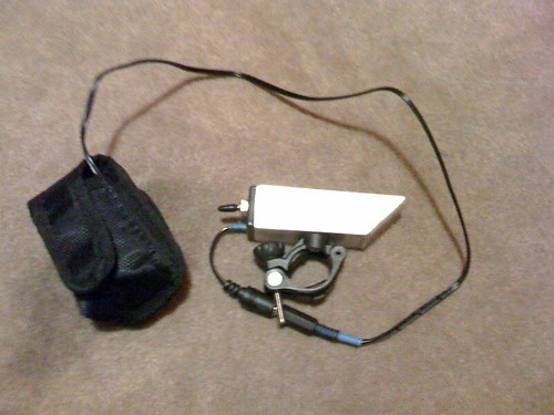
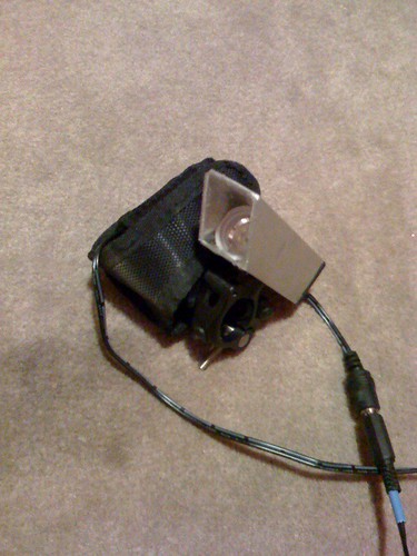
I recently built this DIY Dinotte style light...it's a single XR-E Q5-bin, powered by an 800mA DX driver and 4-AA NiMH battery. Optic is from DX as well.

3394545152_1fdd005b4d.jpg


3394563104_25df832784.jpg


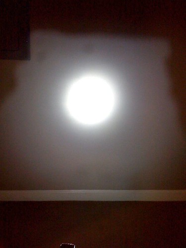
Note how I cut the front of the housing off at a 45-degree angle to create a hood over the optic. My thinking was that it might block some of the upward spill of the beam. I even polished the inside of the hood a little bit with some Al polish. Here's a rough indoor beam-pattern shot:

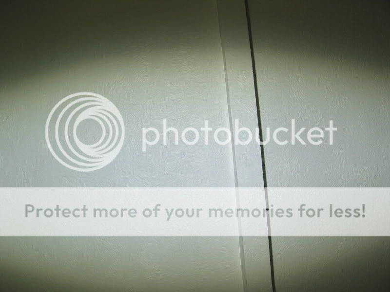
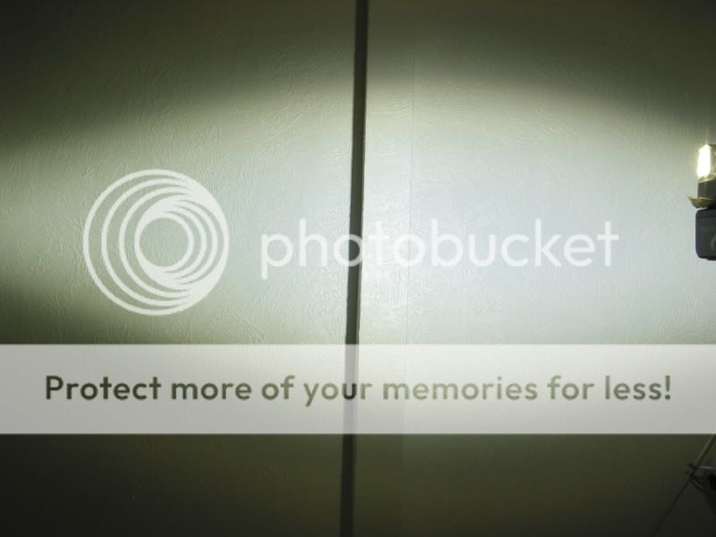
3394555912_cfc3066d2a.jpg


The beam is somewhat trapezoidal in shape, though admittedly this is a far cry from an ECE-style pattern. That said, I got to test the light while riding around last Saturday night, and I am VERY impressed with the usefulness of this light! Aside from just the sheer brightness of this little guy, the optic-hood idea works great: upward spill is controlled, and (presumably since I polished the inside) light is reflected downward immediately in front of the bike, eliminating the dead spot just in front of the front wheel that I've encountered when using other lights. I'd imagine that a longer hood would even work better.

It's a simple concept but one I'm very pleased with, and something I'd encourage others to try!

-Jim G
 
Last edited:

syc

Newly Enlightened
Joined
Jun 10, 2008
Messages
155
Jim,
Cool - the polished hood looks like it paid off!
Since Jim posted his latest stuff, I'll post some photos of my experiments with the MC-E and this aspheric from surplusshed:
L10113_1.jpg


I had also ordered the 12mm diameter aspheric, but found that it was too small to work with. Maybe I'll revisit it later.

Anyway, I wired up an MC-E like this:
2s2pb.jpg


And hooked it up to a power supply. I measured the output across an LED, and it seemed to be delivering about 160ma to the series. Around 1/3 the amount of current that a dynamo would generate, but enough for testing purposes.

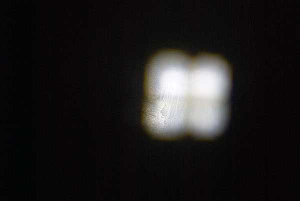
Here's what the beam pattern looked like when the emitters were pretty much in focus:
3420117929_d6090b310d_o.jpg


You can see that the lower 2 emitters are visibly dimmer, but not by a whole lot. Measuring the size of the image of the 4 dies, and the distance from the star to the ceiling, I calculate the angle of the hotspot to be around 8.5 degrees with virtually no spill. A pretty tight pattern for the MC-E. However, there was obviously light from the emitter that wasn't being picked up by the aspheric at the ~20mm focal length. If you look up the radiation pattern for the MC-E, at around 45 degrees off axis, its around the 60% brightness cutoff - the area under this part of the curve is pretty big, but there's still going to be a lot of incidental light that you aren't picking up.

I had a small (25mm diameter) oval diffuser that I placed in front of the aspheric to experiment with a beam pattern that would be good for road use. Here's the result:
3420117937_fb57b7f164_o.jpg


I think the photo overemphasizes the image of the central emitter spot. When I looked at the pattern, it seemed like there was more diffusion than the image shows - goes to show that the human eye and digital camera sensors don't quite operate the same. In any case, it diffused the light across a pretty large strip of the ceiling, with very little light off the axis of diffusion.

I also defocused the lens slightly by bringing it about 4mm closer to the emitter, which would pick up more of the light and spread it out more as well. Here's the result:
3420117945_82b2583411_o.jpg


My camera didn't really pick up the entire beam pattern, but I think you can see that it is a larger, rounded off square. The gradient from top to bottom is even harder to notice in this photo than the first one. However, you still get a very clean cutoff with almost no spill.

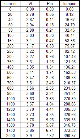
The brightness gradient between the individual dies and the 2 parallel dies just isn't as high as I would have expected. Part of this is probably due to the relatively low current levels ( 160ma vs the 500ma-700ma you often see out of the dynamo), and the fact that the emitters are more efficient at lower currents than higher currents. Looking at jtr1962's excellent test of the R2, here's the table of outputs for the R2 emitters:
Cree_7090_XR-E_bin_R2_lumens.gif


I'm using one of Brum's M-bin MCE's, which comes out to be roughly the same efficiency as the R1 XRE. Close enough to what jtr1962 tested. The series dies are seeing ~160ma apeice for ~60 lumens, while the parallel dies are seeing 80ma for ~32 lumens each. That is about a 30 lumens difference between an upper and lower die.

If we drive the led with a 500ma current, then we'd see 162 lumens for each of the the upper leds, and 92 lumens for each of the lower leds. The efficiency of the led's at lower drive levels actually works against us. Still, we'd end up with a 70 lumen difference between each of the the upper and lower emitters. A 70 lumen difference would be more noticeable I think.

For folks interested in results with the R2, here's the basic emitter projection:
3420926212_268060f317_o.jpg


And here is a slightly defocused beam pattern:
3420926216_a44ae2cc99_o.jpg


The beam pattern is tighter, and less obviously square. Little to no spill, and on the back side of the lens, it was pretty obvious that the aspheric was picking up almost all of the light coming off the emitter. Very little incident light on the other side of the lens. If you want to throw light down the road efficiently, an R2 and this lens would do the trick.

Note that all the photos were taken from the same distance to the ceiling, so you can compare the angles of the hotspots. The defocused R2 is probably around 9-10 degree spread, no spill. The power supply seems to be basically delivering 1 watt of power, adjusting for voltage levels, so the power to the R2 is comparable to the total power for the MCE. All these photos were taken at the same exposure ( F8, 1/20s) and ISO.

Anyways, that's what I've done so far. I don't have anything testable on the road yet, and probably won't for a while since the aspheric lens would need to be mounted properly. But looking around at the hardware store, I think it wouldn't be too hard to rig up a test setup with various pipe fittings, before doing a final housing.
 
Last edited:

John_Galt

Flashlight Enthusiast
Joined
Feb 20, 2009
Messages
1,835
Location
SW, PA
Hows about something with a beam like this

NEWMR16PROJECT052.jpg

NEWMR16PROJECT055.jpg


McTroutlite002.jpg

McTroutlite003.jpg


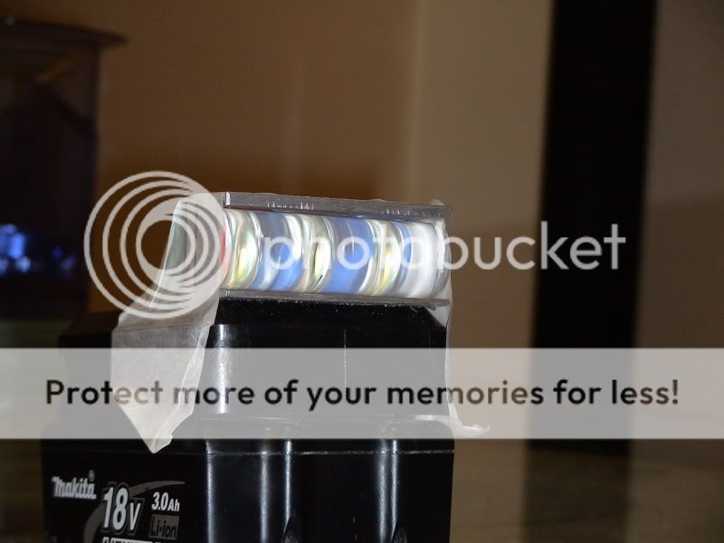
This is just a test rig I am working on experimenting with different sizes of acrylic bar

Now if you used a larger diameter bar and put 2 rows of leds one row dead centre and the other row above and maybe even less leds then to dip switch the centre off and the top on this then drops the beam a good amoumt this i hav not got round to testing yet.


Where did you buy that acrylic bar? That shape looks perfect for an atv light, with a secondary spot light source. Also, can you tell me how many LED's were used, as well as what LED's/drivers were used?
Thanks.
 

msxtr

Newly Enlightened
Joined
Jan 2, 2007
Messages
143
Location
Lleida - Spain
It looks like the Hella HL 2000 uses a collimating optic, yet Peter White reports that it produces an ECE style cutoff beam with gradient brightness:

hl%202000%20bulk%20new%20wb.jpg


(Image from http://www.spanninga.nl/xhtml/product_details.php?cid=9&pid=13)

HL2000-full-power-web.jpg


(This last image from http://www.peterwhitecycles.com/headlights.asp)

Does anyone know more about the optic used in this light?

-Jim G

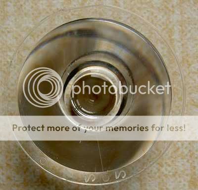
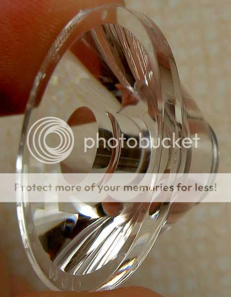
Hi, could are this or is more similar

Optica30mm.jpg


Optica30mm2.jpg


I use with my DIY light and Seoul SSC P4 u-bin leds

3065623918_46654a0426.jpg


Here you can buy this optics

Greetings - Saludos

msxtr
 

sfCyclotourist

Newly Enlightened
Joined
Nov 30, 2006
Messages
93
Hi, could are this or is more similar

Optica30mm.jpg


Optica30mm2.jpg


I use with my DIY light and Seoul SSC P4 u-bin leds

3065623918_46654a0426.jpg


Here you can buy this optics

Greetings - Saludos

msxtr

I highly doubt that those DX optics produce a gradient beam pattern, which is key to an ECE style beam. Please correct me if Im wrong!
 

syc

Newly Enlightened
Joined
Jun 10, 2008
Messages
155

I followed this link and got this error message:
You have an error in your SQL syntax; check the manual that corresponds to your MySQL server version for the right syntax to use near ')' at line 1


I think Spanninga is only a few days from getting p0wn3d by some script kiddies using a SQL injection attack.

In any case, I'm thinking that those TIR reflectors could be shaped like the parabolic reflectors in the BiSY reflectors to get a gradient beam. It might be interesting to take a dremel to one of my optics and round off the top edge. The only question is whether I could polish it up enough afterwards to restore its reflectivity.

EDIT: A quick search on-site shows that simichrome, flitz and jeweler's rouge will polish acrylic. Maybe I'll get some polish and try some optics hacking - and pimp out my VO zeppelin fenders as well!
 
Last edited:
Top