
Following on from 3rd Shifts great tutorials, here's my own.
In this tutorial I plan to show how to build a Maglite 2D fitted with a SSC P4 emitter powered with 2 D cells by a Micropuck boost driver.
Parts list:
Here's a list of where I got all my parts, there are alternatives, so look around for yourself. Bear in mind I'm based in the UK, you may find a better deal depending were you live.
Maglite 2D - This one was custom machined by CPF member RCatR, see here
http://www.candlepowerforums.com/vb/showthread.php?t=160689
Or for a standard maglite (if you are in the UK) www.7dayshop.com have many colours at a good price.
Heatsink - from Warren at Litemania in dealers section see here
http://www.candlepowerforums.com/vb/showthread.php?t=153522
Driver - Luxdrive MicroPuck 2009A SHO 500mA from http://www.ultraleds.co.uk/ .Please note: these were not on the website, but I emailed them and they got some in a couple of weeks (very good customer service).
Conductive glue - I use two part epoxy mixed 50/50 with zinc oxide powder (borrowed from work).
Heat sink compound - RS supplies.
Tool list:
Hacksaw
Pliers
Allen keys
Side cutters
Wire strippers
Soldering iron
A nice cup of tea and biscuit (optional)
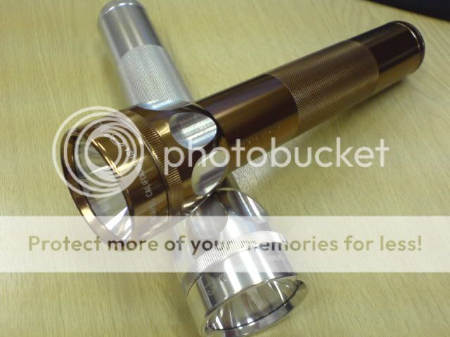
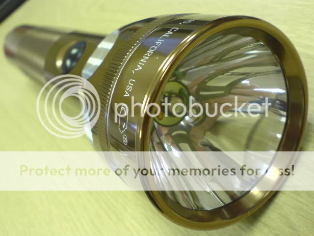
Here's the nice new Maglite 2D
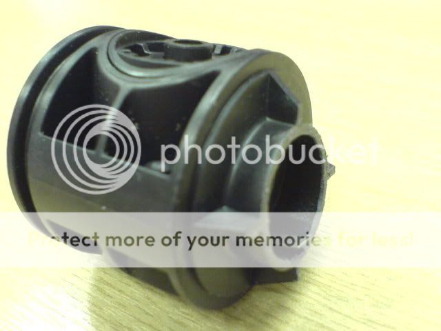
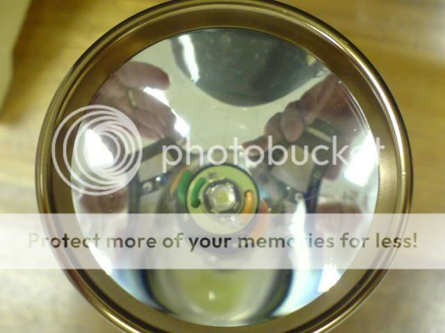
Reflector
Take everything apart. Take the head off the body, unscrew the front and remove the clear lens, o ring and put in a safe place. Take the reflector and cut off the long cammed straight. Leave around 2 to 3mm of tube. BE CAREFUL don't clean any plastic bits off the reflector with your fingers/a rag etc, it will scratch VERY easily.
Sorry forgot to take any pics.
Switch mod and driver
Remove the rubber boot on the switch with fingernails or small screw driver (gently). Undo the hexagon grub screw with an Allen key.
Push the switch down and push it out the back of the body.
Use the same Allen key to undo the bulbholder, remove and throw it in the bin. Cut the long tube down to the base of the switch body.
Cut/snip the negative tag down to the same length as the plastic tube. Solder the black wire of the Micropuck to the negative tag at the bottom, and the red wire to the positive on the side of the switch. You can cover the bare wires with heat shrink tubing as I did, but it's not necessary.
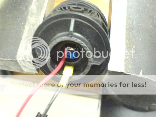
Re-install the switch, place the Micro puck through the Maglite first so that it dangles out the top when the switch is in place. DO NOT PUT BATTERIES IN, the Micropuck will die if powered up without any load (i.e. LED) connected to it. You can guess how I found that out....
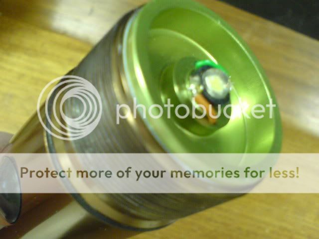
Emitter/Heatsink
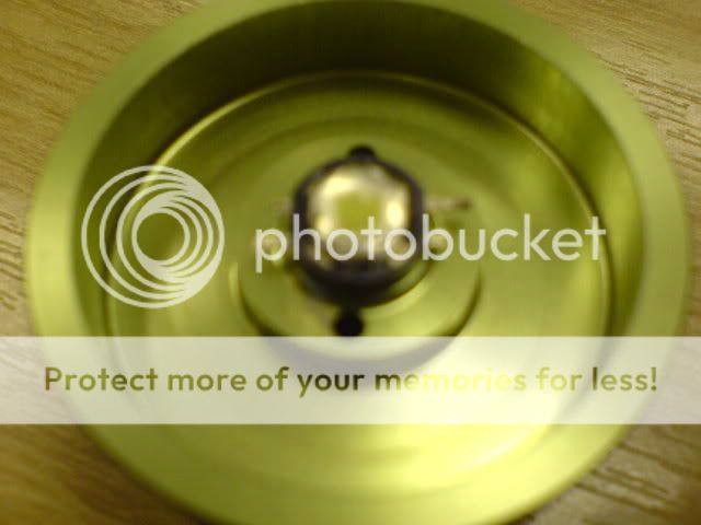
Take the emitter and straighten the two leads gently with a pair of pliers.
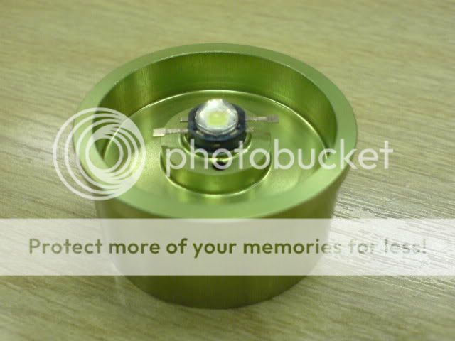
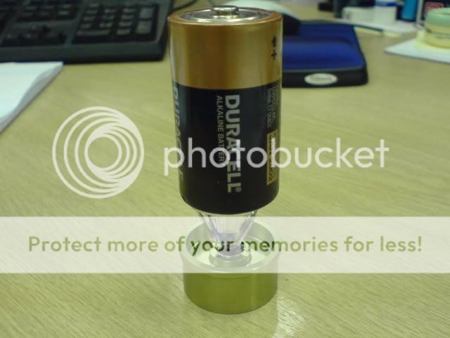
Put the conductive glue on the heatsink and place the emitter. The heat sink from litemania come anodised so there's no need to isolate the SSC emitter base, it also has a locating ring which really helps centre the emitter. Once stuck leave to dry. You can apply slight pressure during curing, I did this with an old 27mm optic and a battery.
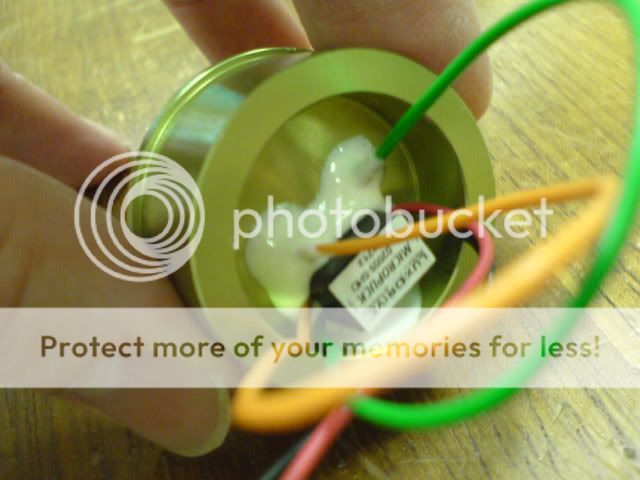
Wire up emitter
Once dry, you now have to solder the output leads from the micropuck to the emitter. Before that, you need to cut down the emitter leads. I just used a pair of side cutters.
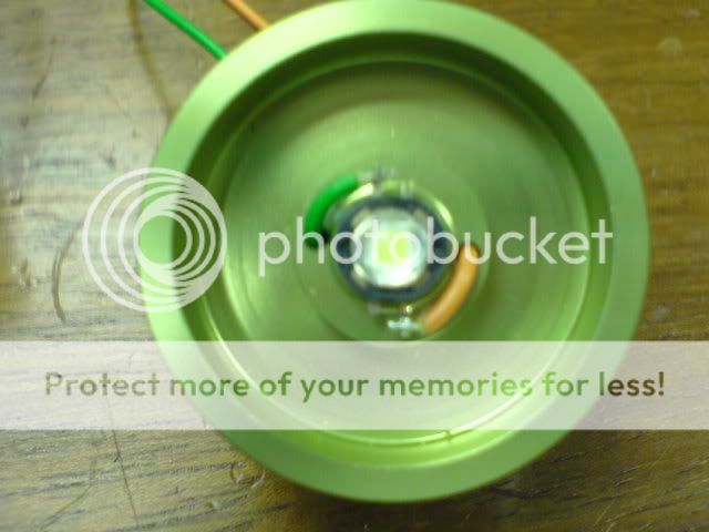
Now tin the emitter leads and the driver wires with solder. Pass the two wires through the heatsink holes and solder to the emitter leads. Steady hands required. Make sure you get the wires the correct way round.
Green = Negative
Orange = Positive
The negative side of the emitter has a "U" shape removed from the metal.
Now you can put some batteries in an check it works before final assembly.
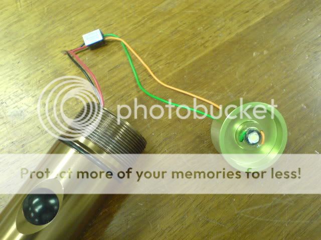
I don't like parts rattling around, so I glued the driver down to the underside of the heatsink, and place some more glue around the holes where the two wires enter to prevent any movement during use.
Once the glue has set, insert the heatsink into the Maglite. Put some heatsink compound around the heatsink to ensure good heat transfer to the body of the maglite.
Be aware that depending on the colour finish the fit of the heatsink can be loose or tight. If tight you will need to sand the inside of the maglite. This one was loose, so I used a centre punch on the outside of the heatsink to make four burrs, which made a tight fit.
Now screw on the head and power up.
Other stuff:
If you want a more powerful output you can use two micropucks, that should give around 850 to 900mA to the emitter, but run time will be reduced.
I've not had time to take any current measurements, Lux measurements or beamshots, I'll try to update over the coming weeks.
Now go, build, enjoy.
In this tutorial I plan to show how to build a Maglite 2D fitted with a SSC P4 emitter powered with 2 D cells by a Micropuck boost driver.
Parts list:
Here's a list of where I got all my parts, there are alternatives, so look around for yourself. Bear in mind I'm based in the UK, you may find a better deal depending were you live.
Maglite 2D - This one was custom machined by CPF member RCatR, see here
http://www.candlepowerforums.com/vb/showthread.php?t=160689
Or for a standard maglite (if you are in the UK) www.7dayshop.com have many colours at a good price.
Heatsink - from Warren at Litemania in dealers section see here
http://www.candlepowerforums.com/vb/showthread.php?t=153522
Driver - Luxdrive MicroPuck 2009A SHO 500mA from http://www.ultraleds.co.uk/ .Please note: these were not on the website, but I emailed them and they got some in a couple of weeks (very good customer service).
Conductive glue - I use two part epoxy mixed 50/50 with zinc oxide powder (borrowed from work).
Heat sink compound - RS supplies.
Tool list:
Hacksaw
Pliers
Allen keys
Side cutters
Wire strippers
Soldering iron
A nice cup of tea and biscuit (optional)
Here's the nice new Maglite 2D
Reflector
Take everything apart. Take the head off the body, unscrew the front and remove the clear lens, o ring and put in a safe place. Take the reflector and cut off the long cammed straight. Leave around 2 to 3mm of tube. BE CAREFUL don't clean any plastic bits off the reflector with your fingers/a rag etc, it will scratch VERY easily.
Sorry forgot to take any pics.
Switch mod and driver
Remove the rubber boot on the switch with fingernails or small screw driver (gently). Undo the hexagon grub screw with an Allen key.
Push the switch down and push it out the back of the body.
Use the same Allen key to undo the bulbholder, remove and throw it in the bin. Cut the long tube down to the base of the switch body.
Cut/snip the negative tag down to the same length as the plastic tube. Solder the black wire of the Micropuck to the negative tag at the bottom, and the red wire to the positive on the side of the switch. You can cover the bare wires with heat shrink tubing as I did, but it's not necessary.
Re-install the switch, place the Micro puck through the Maglite first so that it dangles out the top when the switch is in place. DO NOT PUT BATTERIES IN, the Micropuck will die if powered up without any load (i.e. LED) connected to it. You can guess how I found that out....
Emitter/Heatsink
Take the emitter and straighten the two leads gently with a pair of pliers.
Put the conductive glue on the heatsink and place the emitter. The heat sink from litemania come anodised so there's no need to isolate the SSC emitter base, it also has a locating ring which really helps centre the emitter. Once stuck leave to dry. You can apply slight pressure during curing, I did this with an old 27mm optic and a battery.
Wire up emitter
Once dry, you now have to solder the output leads from the micropuck to the emitter. Before that, you need to cut down the emitter leads. I just used a pair of side cutters.
Now tin the emitter leads and the driver wires with solder. Pass the two wires through the heatsink holes and solder to the emitter leads. Steady hands required. Make sure you get the wires the correct way round.
Green = Negative
Orange = Positive
The negative side of the emitter has a "U" shape removed from the metal.
Now you can put some batteries in an check it works before final assembly.
I don't like parts rattling around, so I glued the driver down to the underside of the heatsink, and place some more glue around the holes where the two wires enter to prevent any movement during use.
Once the glue has set, insert the heatsink into the Maglite. Put some heatsink compound around the heatsink to ensure good heat transfer to the body of the maglite.
Be aware that depending on the colour finish the fit of the heatsink can be loose or tight. If tight you will need to sand the inside of the maglite. This one was loose, so I used a centre punch on the outside of the heatsink to make four burrs, which made a tight fit.
Now screw on the head and power up.
Other stuff:
If you want a more powerful output you can use two micropucks, that should give around 850 to 900mA to the emitter, but run time will be reduced.
I've not had time to take any current measurements, Lux measurements or beamshots, I'll try to update over the coming weeks.
Now go, build, enjoy.
