
Fireclaw18
Flashlight Enthusiast
- Joined
- Mar 16, 2011
- Messages
- 2,408
Awhile back I purchased a DQG 18650 Tiny III clicky. This light has some impressive features. It's the smallest 18650 light on the market. It has a very clever self-adjusting battery compartment with no springs. Instead the whole compartment changes length to accomodate different sized 18650s.
There were a few things I didn't like about it though. The UI didn't have a shortcut to max and left a lot to be desired. The maximum output was lower than the pocket rockets I'm used to. And the protruding sideswitch was easy to accidentally activate in the pocket. I decided to see if I could address these concerns through modding.
The bezel was held on with a small amount of clear threadlocker. It came off fairly easily using 3M rubber indoor stairway grip tape. With the bezel off, the TIR falls out revealing the driver.

To save space, this light has just a single board that contains both the driver and star. It's at least 20mm wide. The switch is fully recessed into the head of the light and has 2 tiny wires connecting it to the driver. I decided to use the stock switch, but replace the driver with one from Mountain Electronics and make it a triple. Since the Carclo triple TIR is around 7mm shorter than the stock TIR, I figured there should be plenty of room for the new driver and the separate star.
Unfortunately, almost immediately I hit a major problem. I couldn't remove the head from the body. They must've used a ton of threadlocker. I tried grip tape on both the head and body. When that didn't work I used 2 sets of pliers on the grip tape. I also tried hot melt glue instead of grip tape. And I tried freezing it and using a hot air gun. Nothing worked. I think to separate those pieces will probably require heating the head and body to 350 degrees to melt the threadlocker, but doing so could destroy the switch and anodizing.
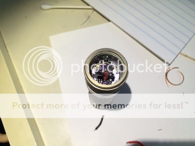
I gave up on removing the head and instead decided to drill out most of the stock driver and mount the new parts to its remains. First I desoldered and removed the switch wires. I planned to reuse those. Then I touched a soldering iron against the side of the LED and heated till the LED popped off. Then I drilled a small hole in the center of the driver (from the top). I used a countersink bit to drill all the way through, then scraped off any remaining SMDs with a screwdriver and then finished it with a handfile. Here's what it looked like:

For negative contact my hope was that I could find a leftover trace on the stock driver that still connected to the body tube. If that didn't work my plan was to drill a hole through the side of the tube and attach a wire bypass. Fortunately, I lucked out: I found a leftover via just below the switch button that according to my DMM had a clean negative contact to the body tube.
I decided to mount the new driver just below the old driver. I was using a BLF17DD driver with a flat bottom. I removed its spring and replaced it with a copper disk. Despite being mounted directly below the original driver, this didn't actually reduce the size of the battery compartment as the original driver was much thicker. Checking my driver, I noticed that the outer pin of the MCU could actually sit right next to the negative contact via.
Before attaching the driver, I used arctic alumina to pot anything at the edges that I didn't want to get accidental negative contact. Then I pressed it into position and used a few touches of arctica alumina from the sides to hold it into place. After that had cured, I soldered the via to the outer pin of the MCU and reattached the switch wires. I put a little Kapton tape over the switch wires to provide extra security.
I figured there was room for a small copper heatsink platform for the star to rest on. I laminated 3 pieces of copper sheet with solder and cut and filed them into shape. To keep the heatsink and star at the right height, I bent a piece of copper into a ring and rested it on the ledge formed from the remains of the stock driver. It took a little trial and error to get the copper ring to just the right thickness. I also had to file the star slightly so it would fit into the light. Here's a picture of the star, heatsink and copper ring (the flat area in the heatsink and star is to provide clearance for the switch wires):

The light is currently equipped with triple XPG2 in 3 different tints. I used a Carclo 10507 optic. To get the optic to fit I had to slightly file down the outer edges of the optic's legs.
Finally, I place a glass lens just in front of the optic. The opening in the bezel is exactly 20mm wide. Without a lens, a 20mm Carclo optic will fall out of this hole. I'd bought a 22 mm lens for this purpose from flashlightlens.com, but it proved to be slightly too wide. I used fine sandpaper to grind it down to 21mm. Then I screwed everything together. Here's a picture of the assembled light next to an unmodified DQG 18650 clicky:
I still had the problem of the switch being too sensitive. To fix this I drilled a hole through a piece of 0.064" piece of aluminum sheet than filed it by hand to the right shape. I then epoxied this cover around the outer switch. It turned the protruding metal button into a deeply recessed one making accidental pocket activation very unlikely. Here's a picture with the cover installed:

A side benefit is this cover acts as an antiroll device.
Stock DQG18650 on left, triple on the right:
Here's another of the triple on left and stock on right (taken before I mounted the switch cover):

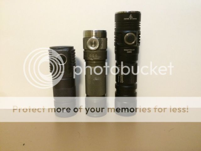
Three modified triples! Left is my Convoy S2+ mini with triple XPL running on 18500, middle is the DQG18650 mini clicky triple, right is a modded Sunwayman C20C with triple XPG2. All 3 lights have electronic switch FET drivers.
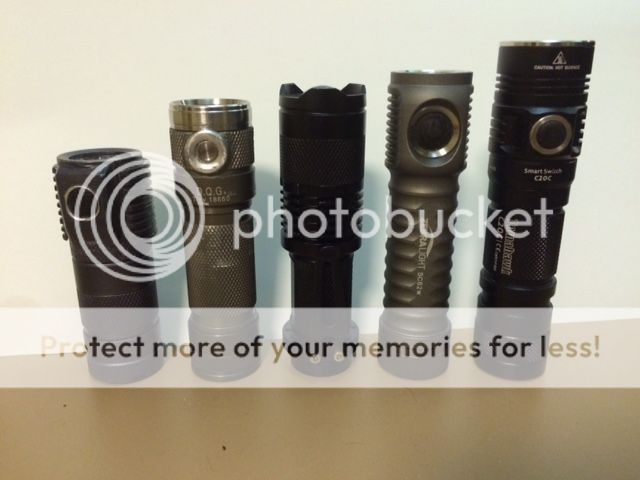
Same as above but with a Sipik 68 and Zebralight SC62w added to the picture.
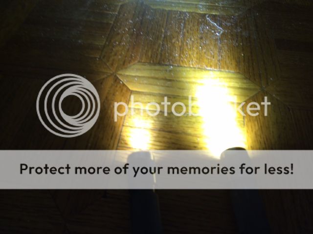
I'm pretty happy with how this came out even though I dinged up the anodizing pretty badly trying to remove the head. At a guess I figure the modded DQG outputs 1700-2000 lumens max at turn-on, but it gets hot very fast at that setting.
There were a few things I didn't like about it though. The UI didn't have a shortcut to max and left a lot to be desired. The maximum output was lower than the pocket rockets I'm used to. And the protruding sideswitch was easy to accidentally activate in the pocket. I decided to see if I could address these concerns through modding.
The bezel was held on with a small amount of clear threadlocker. It came off fairly easily using 3M rubber indoor stairway grip tape. With the bezel off, the TIR falls out revealing the driver.

To save space, this light has just a single board that contains both the driver and star. It's at least 20mm wide. The switch is fully recessed into the head of the light and has 2 tiny wires connecting it to the driver. I decided to use the stock switch, but replace the driver with one from Mountain Electronics and make it a triple. Since the Carclo triple TIR is around 7mm shorter than the stock TIR, I figured there should be plenty of room for the new driver and the separate star.
Unfortunately, almost immediately I hit a major problem. I couldn't remove the head from the body. They must've used a ton of threadlocker. I tried grip tape on both the head and body. When that didn't work I used 2 sets of pliers on the grip tape. I also tried hot melt glue instead of grip tape. And I tried freezing it and using a hot air gun. Nothing worked. I think to separate those pieces will probably require heating the head and body to 350 degrees to melt the threadlocker, but doing so could destroy the switch and anodizing.
I gave up on removing the head and instead decided to drill out most of the stock driver and mount the new parts to its remains. First I desoldered and removed the switch wires. I planned to reuse those. Then I touched a soldering iron against the side of the LED and heated till the LED popped off. Then I drilled a small hole in the center of the driver (from the top). I used a countersink bit to drill all the way through, then scraped off any remaining SMDs with a screwdriver and then finished it with a handfile. Here's what it looked like:

For negative contact my hope was that I could find a leftover trace on the stock driver that still connected to the body tube. If that didn't work my plan was to drill a hole through the side of the tube and attach a wire bypass. Fortunately, I lucked out: I found a leftover via just below the switch button that according to my DMM had a clean negative contact to the body tube.
I decided to mount the new driver just below the old driver. I was using a BLF17DD driver with a flat bottom. I removed its spring and replaced it with a copper disk. Despite being mounted directly below the original driver, this didn't actually reduce the size of the battery compartment as the original driver was much thicker. Checking my driver, I noticed that the outer pin of the MCU could actually sit right next to the negative contact via.
Before attaching the driver, I used arctic alumina to pot anything at the edges that I didn't want to get accidental negative contact. Then I pressed it into position and used a few touches of arctica alumina from the sides to hold it into place. After that had cured, I soldered the via to the outer pin of the MCU and reattached the switch wires. I put a little Kapton tape over the switch wires to provide extra security.


I figured there was room for a small copper heatsink platform for the star to rest on. I laminated 3 pieces of copper sheet with solder and cut and filed them into shape. To keep the heatsink and star at the right height, I bent a piece of copper into a ring and rested it on the ledge formed from the remains of the stock driver. It took a little trial and error to get the copper ring to just the right thickness. I also had to file the star slightly so it would fit into the light. Here's a picture of the star, heatsink and copper ring (the flat area in the heatsink and star is to provide clearance for the switch wires):

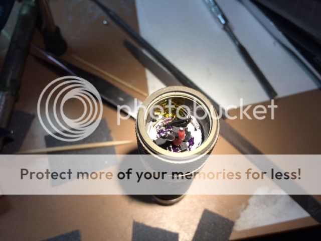
The light is currently equipped with triple XPG2 in 3 different tints. I used a Carclo 10507 optic. To get the optic to fit I had to slightly file down the outer edges of the optic's legs.
Finally, I place a glass lens just in front of the optic. The opening in the bezel is exactly 20mm wide. Without a lens, a 20mm Carclo optic will fall out of this hole. I'd bought a 22 mm lens for this purpose from flashlightlens.com, but it proved to be slightly too wide. I used fine sandpaper to grind it down to 21mm. Then I screwed everything together. Here's a picture of the assembled light next to an unmodified DQG 18650 clicky:

I still had the problem of the switch being too sensitive. To fix this I drilled a hole through a piece of 0.064" piece of aluminum sheet than filed it by hand to the right shape. I then epoxied this cover around the outer switch. It turned the protruding metal button into a deeply recessed one making accidental pocket activation very unlikely. Here's a picture with the cover installed:

A side benefit is this cover acts as an antiroll device.
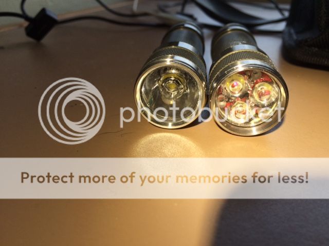
Stock DQG18650 on left, triple on the right:

Here's another of the triple on left and stock on right (taken before I mounted the switch cover):

Three modified triples! Left is my Convoy S2+ mini with triple XPL running on 18500, middle is the DQG18650 mini clicky triple, right is a modded Sunwayman C20C with triple XPG2. All 3 lights have electronic switch FET drivers.

Same as above but with a Sipik 68 and Zebralight SC62w added to the picture.

I'm pretty happy with how this came out even though I dinged up the anodizing pretty badly trying to remove the head. At a guess I figure the modded DQG outputs 1700-2000 lumens max at turn-on, but it gets hot very fast at that setting.

