shining beam 2500mA driver wiring?

Mettee

Enlightened
Joined
Aug 5, 2008
Messages
678
Location
Arizona
That negative solder joint might be touching that star it looks like but I cant tell for sure. Ti force had that happen to him a while back.

I usually clip the gold spring off and then de-solder what is left as well. Its hard as heck to get off unless you do that because the heat
just gets soaked up. But I would not say that that is the issue at all.

Let me test one I have with a low VF P7(dsvni) and I will let you know what I get with mine. I have a few of the SB boards.

drew


OH and you might want to resize those images or the mods will tell you to.
 
Last edited:

jez

Newly Enlightened
Joined
Apr 22, 2010
Messages
29
Thanks for the warning Mettee on the re size!

I'm going to DD the led later and see what I get.

I soldered the +ve to the board in the middle of the spring as knowing my luck I would have ripped the board to pieces.

I thought the stars just changed the modes but they all had high?
 

Mettee

Enlightened
Joined
Aug 5, 2008
Messages
678
Location
Arizona
The stars do change the modes but you have to cut the other trace and solder to another star to make it work, if you didnt do that and you also have solder on another star you may be having a problem....
 

jez

Newly Enlightened
Joined
Apr 22, 2010
Messages
29
OK, direct drive gives me 2.3A so does that mean that i'm losing the current through the driver and I should have got a boost driver instead?

about the stars, thanks.
 

uk_caver

Flashlight Enthusiast
Joined
Feb 9, 2007
Messages
1,408
Location
Central UK
Taking the nominal ~120mV dropout voltage of the AMC7135 chips, and applying it to the slope of the P7's voltage/current graph at the relevant current, assuming that the battery voltage hadn't changed meaningfully with the different loads, and that any extra connections were negligible resistance, that 120mV would look likely to cost ~750mA compared to direct drive, which seems pretty much what you found

However, one thing that should be remembered is that the meter measuring the current also introduces some resistance.
On my cheap and relatively cheap meters, on the high current ranges, that resistance seems to be something like an extra 0.1ohm (300-350mV at 3A)
From the manual, it looks like your Fluke meter is rather better - around 0.037 ohm, (assuming probe contact is perfect?), but even then, that'd *still* be costing you 50+mV at 1.5A, enough to quite meaningfully change the current that the LED could end up taking, maybe by ~350-400mA.

(Doing direct drive current measurements, or doing linear regulator current measurements when there's no voltage 'headroom' to play with can be a real pain.)

Also, have you actually run the P7 for any length of time, or just done very cautious short bursts?
I found with a couple of P7s I bought that the Vf permanently dropped after even only a few minutes of 'burning in' at ~2.5A, even with the LEDs properly heatsinked. That just seems to be something that generally happens.
Also bear in mind that the Vf will reversibly drop a little as the P7 heats up in use, so unless heatsinking is perfect, it could be that without the meter in place, you could possibly get a rather higher output than 1.5A even with the driver in place, at least on fresh cells.

Would you have any way of checking that out (like a lightmeter, or a digital camera with manual settings that you could use to illuminate a scene and take both cold, meter-in-circuit and warm, no-meter-in-circuit pictures with)?

Even if that was more encouraging, it could still mean that you'd lose brightness as the cells discharge, possibly fairly significantly, but things might not be quite as bad as they might seem with a meter in circuit.

With the meter in place, have you done cold and warm readings for direct drive and/or driver-based drive?
 
Last edited:

jez

Newly Enlightened
Joined
Apr 22, 2010
Messages
29
[/COLOR]
Taking the nominal ~120mV dropout voltage of the AMC7135 chips, and applying it to the slope of the P7's voltage/current graph at the relevant current, assuming that the battery voltage hadn't changed meaningfully with the different loads, and that any extra connections were negligible resistance, that 120mV would look likely to cost ~750mA compared to direct drive, which seems pretty much what you found

However, one thing that should be remembered is that the meter measuring the current also introduces some resistance.
On my cheap and relatively cheap meters, on the high current ranges, that resistance seems to be something like an extra 0.1ohm (300-350mV at 3A)
From the manual, it looks like your Fluke meter is rather better - around 0.037 ohm, (assuming probe contact is perfect?), but even then, that'd *still* be costing you 50+mV at 1.5A, enough to quite meaningfully change the current that the LED could end up taking, maybe by ~350-400mA.

(Doing direct drive current measurements, or doing linear regulator current measurements when there's no voltage 'headroom' to play with can be a real pain.)
Good explanation thanks.

Also, have you actually run the P7 for any length of time, or just done very cautious short bursts?
I found with a couple of P7s I bought that the Vf permanently dropped after even only a few minutes of 'burning in' at ~2.5A, even with the LEDs properly heatsinked. That just seems to be something that generally happens.
Also bear in mind that the Vf will reversibly drop a little as the P7 heats up in use, so unless heatsinking is perfect, it could be that without the meter in place, you could possibly get a rather higher output than 1.5A even with the driver in place, at least on fresh cells.
I've not run the torch for long tests as it's my work one so I fiddle when I can.

Would you have any way of checking that out (like a lightmeter, or a digital camera with manual settings that you could use to illuminate a scene and take both cold, meter-in-circuit and warm, no-meter-in-circuit pictures with)?

Even if that was more encouraging, it could still mean that you'd lose brightness as the cells discharge, possibly fairly significantly, but things might not be quite as bad as they might seem with a meter in circuit.

With the meter in place, have you done cold and warm readings for direct drive and/or driver-based drive?
I'm sorry but being new to this the camera shots look a little beyond me at the moment. Not being very helpful am I?

Mettee, in another thread ssc P7 questions you recommended a D bin P7 for holdthat1 who was also going for NiMH.
Do you think that would help?

Thanks
 

Mettee

Enlightened
Joined
Aug 5, 2008
Messages
678
Location
Arizona
I thought you said you had a D bin from shadowkeeper so you should be fine there.

You could also try adding a 4th battery in there to see if that changes the amps you see at the tail.
That will combat voltage drop for a test. You never know maybe you have a J bin P7 with a higher VF.

I have not had a chance to test a set up here yet.
 
Last edited:

jez

Newly Enlightened
Joined
Apr 22, 2010
Messages
29
The led is this one
Seoul Semiconductor's P7 Emitters (W724C0-DSWOI)
"AVAILABLE"
Flux bin D: 800 - 900 lumen output at 2.8A
Color bin SW0: 6050K
Vf bin I: 3.25 - 3.50V

Is this a D bin or I bin? The other one that is out of stock also says flux bin D but Vf bin J.

I'm going to have to leave the LED direct drive until I come back on shift on Sunday but I will try the 4 d cells then to see what I get.

Perhaps this was not as straight forward as I hoped? Huge learning curve though :)

I'll keep an eye on the thread to see what you might be able to come up with in the mean time.

Thanks again for helping out a newb

Jez.
 

ti-force

Flashlight Enthusiast
Joined
Jan 14, 2009
Messages
1,266
Location
Georgia, U.S.
The led is this one
Seoul Semiconductor's P7 Emitters (W724C0-DSWOI)
"AVAILABLE"
Flux bin D: 800 - 900 lumen output at 2.8A
Color bin SW0: 6050K
Vf bin I: 3.25 - 3.50V

Is this a D bin or I bin? The other one that is out of stock also says flux bin D but Vf bin J.

I'm going to have to leave the LED direct drive until I come back on shift on Sunday but I will try the 4 d cells then to see what I get.

Perhaps this was not as straight forward as I hoped? Huge learning curve though :)

I'll keep an eye on the thread to see what you might be able to come up with in the mean time.

Thanks again for helping out a newb

Jez.


Yes, it's definitely a learning curve:thumbsup:.


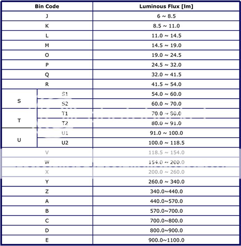
As for your emitter information. You need to look at the data sheet for each emitter. DSWOI is actually 3 different bin codes for your emitter. The first letter, "D" is the luminous flux bin code. Below is the corresponding chart:


SSCP7FluxBininfo.jpg


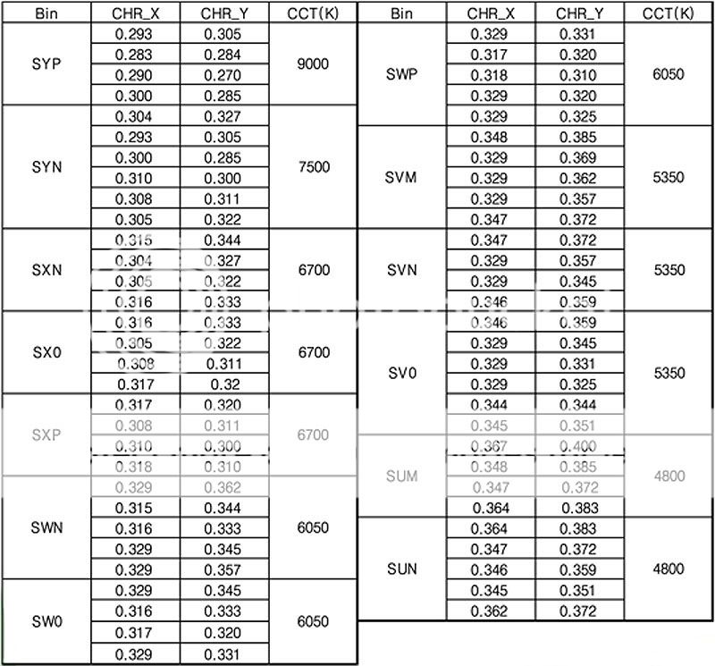
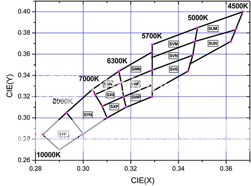
The next 3 letters, "SWO" is the tint bin code. Below are the corresponding charts
:

SSCP7ColorBin.jpg

SSCP7ColorBinKelvinChart.jpg


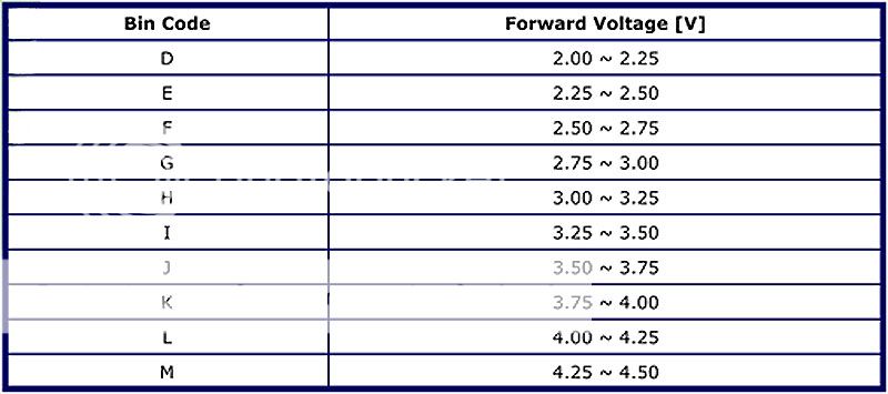
The last letter, "I" is the forward voltage bin code. Below is the corresponding chart:


SSCP7VoltageForwardChart.jpg


Maybe this will help you make better sense of things. Unfortunately, every emitter manufacturer labels their emitters a little differently, so you will have to read the data sheet for each emitter to make sense of all of the bins that are labeled:thumbsup:.


BTW, posted images can have a maximum size of 800x800. As long as you stay exactly 800x800 or smaller, you're good to go.
 
Last edited:

daytec

Newly Enlightened
Joined
Sep 14, 2009
Messages
57
Location
garner ,nc
I am running the same driver with a linger special . With a single 18650 i get around 1.5a with two 123's {6v} i get a full 2.5a. Nailbender gave me this tip [thanks dave]. try raising the input volts. hope this helps.........marty
 

jez

Newly Enlightened
Joined
Apr 22, 2010
Messages
29
Thanks ti-force & daytec.

really wanted to keep to 3 nimh as it's easier to look after at work - free equipment ;-)

I did try 3 alkalines and 4.5V ish still gave 1.5A at switch on but i'll try 4 nimh and see if there is a difference.
 

Mettee

Enlightened
Joined
Aug 5, 2008
Messages
678
Location
Arizona
so try a 4th battery like many of us have said and see what that does...then go from there and post results.

If you are sure you have a DxxxI binned P7 that is not the problem. If you are running alks that may be part of the problem, try NIMHs.
 

jez

Newly Enlightened
Joined
Apr 22, 2010
Messages
29
Mettee,

I am running NiMH, 3 x 10000 mAH Ansmann. just tried the alks for the higher voltage.

Good to hear P7 is ok.
 

ti-force

Flashlight Enthusiast
Joined
Jan 14, 2009
Messages
1,266
Location
Georgia, U.S.
Mettee,

I am running NiMH, 3 x 10000 mAH Ansmann. just tried the alks for the higher voltage.

Good to hear P7 is ok.

The alkalines will have severe voltage sag and the current reading you got is probably the best they will do. Try 4 NiMh's and your problem might be solved. I wonder if a different brand of NiMh's would perform better than the ones you're using? Just wondering; I've never heard of the brand you're using, but I have never used NiMh's much, so I was just curious.
 
Last edited:

Mettee

Enlightened
Joined
Aug 5, 2008
Messages
678
Location
Arizona
Ti maybe he can try a single lithium ion, what do you think? At least if he has one to try...

I had good luck with alks and I used them for a while with my very first build that was a P7 build. I am tending to think it might be something else that is wrong...just sayin...

Ok I tried my P7 with SB board...both a single lion, 3-4 alks and/or eneloops provide over 2 amps. Yes the 4 alks has been drained a bit so I did not over voltage the board, and I did also try with 3 new fresh ones. So i am lost as to what the issue is.

How is the solder connection to the led? Unless you tried your 4th nimh and that solved the problem.
 
Last edited:

ti-force

Flashlight Enthusiast
Joined
Jan 14, 2009
Messages
1,266
Location
Georgia, U.S.
Ti maybe he can try a single lithium ion, what do you think? At least if he has one to try...

I had good luck with alks and I used them for a while with my very first build that was a P7 build. I am tending to think it might be something else that is wrong...just sayin...

I can say this about the Li-ion setup. I have a 2d Mag, with a 7135 based driver (9- 7135 chips for 3+A current), a CSXPI SSC P7 emitter, using 1- Batterspace 26650 and it works flawlessly. But I've learned that the internal resistance of batteries can play a serious role in delivering the current. AW batteries almost always perform as expected, but I had problems with some DX D-sized Li-ions. I have 2 of those, and neither one would deliver over 2.5A in this light, but the Batteryspace delivers over 3.1A.

I only use Lithium batteries, but that's personal preference. Also, I can't recommend the use of Li-ion batteries without giving a warning of their dangers in the same sentence. If anyone reading this isn't familiar with the dangers of misusing or neglecting Li-ion batteries, I strongly recommend you research that prior to using them.

It's really hard to diagnose a problem like this through a computer, but we're trying. If the raised input voltage doesn't change anything, we'll try something else, and hopefully someone will figure out what's causing the problem:thumbsup:
 

Essexman

Flashlight Enthusiast
Joined
Oct 9, 2006
Messages
1,192
Location
U.K.
Hope you can sort this out?

All is not lost, if 4 NiMH cells work the driver correctly, you can still use your 3D mag. You can fit 4 C NiMH into a 3D mag with ease, it's a common mod.

Let us know how you get on.
 

jez

Newly Enlightened
Joined
Apr 22, 2010
Messages
29
I really appreciate all your efforts with this.

Was 2.3A about right for direct drive?

The torch is at work right now and I can't get to it till Sunday but getting this list of things to try is promising.

I soldered the led using both the legs with the wire laying across them as it was easier this way without a third pair of hands. Will that make a difference?

How is the front of the board connected to the back? Could one half of the boards regulators not be connected somehow?

I have found 4 C size NiMH at home of the same make Ansmann so i'll take them to work and try those also.

I'll try different wire too and see what happens. Can't imagine a different make of 24AWG will make much difference but maybe a fresh go at soldering will give better connections?

Mettee did you measure the current through the tailcap?

Thanks Guys
 

Webbstarr

Newly Enlightened
Joined
Feb 8, 2010
Messages
9
I have the same boards from SB but mine do not have what looks like a small resistor soldered below the spring on post #3. could this be the issue? im curious because i have the same hardware and want to build one as well. i however will be using imr 26650's. good luck :popcorn:
 

TorchBoy

Flashlight Enthusiast
Joined
Jan 15, 2007
Messages
4,486
Location
New Zealand
You could also try adding a 4th battery in there to see if that changes the amps you see at the tail.
That will combat voltage drop for a test.
That should do it. Last month I made a headlamp using AMC7135 drivers that on high feeds three XP-G LEDs at 1 A each (3 A total). Unfortunately there is voltage voltage drop all over the place and with a bit of voltage sag from three NiMH (Eneloops) the LEDs were only getting a total 1.0 A or so, or maybe as much as 1.2 A hot off the charger. I added a 4th NiMH cell and that brought it up to the full 3 A I was expecting. :twothumbs It still drops out of regulation before the cells are empty, though.

Good luck with the 4 C cells. :popcorn:
 
Top