TorchBoy
Flashlight Enthusiast
The total current from an array of AMC7135s is much less of an issue than how many volts each AMC7135 is dropping and how they can get rid of their heat.

I have run tons and tons of these with no "cooling" at 3.0 amps and they never have problems. I have done 1 sandwich that had a problem and I was never able to see that one again after I sent it off.
you would also think that with 3 SST-50s they would hit a thermal cut off before this light would....especially at over 4 amps.

If the cooling the board is getting is reasonable, perhaps it doesn't need a complete extra (4th) cell to get the volts for full output. That's a bit awkward. Perhaps four cells could be used, but with some extra resistance introduced somewhere. :shrug:
, but that's the setup I have, which is why I like it, plus I have a 2D Mag, which is shorter. Also, I understand that Li-xxxx's aren't for everyone.I dare say that'll only get it to run in regulation for a short time when the 3 cells are freshly charged. Because four flat NiMHs will give fewer volts than 3 fully charged NiMHs, 4 cells will likely drop out of regulation at some point too. How much current does it provide when the 3 or 4 batteries are half or almost completely flat? Is either OK?
Justin is probably right about the thermal limiting, but I didn't get that in my headlamp. Can you cool them easily?
I have run tons and tons of these with no "cooling" at 3.0 amps and they never have problems. I have done 1 sandwich that had a problem and I was never able to see that one again after I sent it off.
you would also think that with 3 SST-50s they would hit a thermal cut off before this light would....especially at over 4 amps.
I understand what you guys are saying.
I just dont think that is enough to make it do what it is doing...he has a problem with 3 cells. charged they should be over 4v and should easily supply the voltage to hit is mark of 2.8a. Something else is happening here that is being missed. I used 3 AA eneloops with the same board and a DxxxI P7 and it was over 2.xx amps for the whole test. With 4 it was still 2.xx amps the entire test. I can not remember what voltage it was for both. But I have also used 2 lion on these boards just to see what it would do and it never acted like described by the OP(admittedly not for long periods). And I would figure that is an over voltage above the VF if there was ever any.
For the driver heatsinking, do you glue the aluminium disc to the top of the drivers? No need to touch the actual circuit board? Now thats a newb question
I think I can change the battery wires for 20 gauge but I don't think these will go through the heatsink holes. Would just the bare conductor be ok for testing knowing the heatsink is HAIII anodised?
http://www.ansmann.de/cms/businessd...argeable-batteries-nimh/mono-d/10000-mah.html
The driver is just hanging free at the moment with no additional heatsinking.
It's frustrating for me having to ask all this as it seemed a fairly common and straight forward mod so problems should have been minimal.
For the driver heatsinking, do you glue the aluminium disc to the top of the drivers? No need to touch the actual circuit board? Now thats a newb question


I've got hold of a second DMM if that helps for measurements.
I think I can change the battery wires for 20 gauge but I don't think these will go through the heatsink holes. Would just the bare conductor be ok for testing knowing the heatsink is HAIII anodised?
I've just tried 4 c's with it all hanging free and as the current started to drop I touched the regs on both sides of the driver and almost burnt my finger so they are getting damn hot. Guess that's that for 4 cells. Can't imagine any heatsinking stopping them cooking.
2.35A (tailcap) and 3.3 Vf (led) with 3 d's measured one after the other. Seems my d's are either getting better or something else is settling in?
regs are fine at this current to touch.
 . I had issues with my first SSC P7 build too, in fact, that's where I cut my teeth, and I've been learning ever since, although, the basics make a lot better sense to me now. I have to thank Linger, JustinCase and TorchBoy for helping me a LOT with my problems. If not for them, I'd still be lost:thumbsup:.
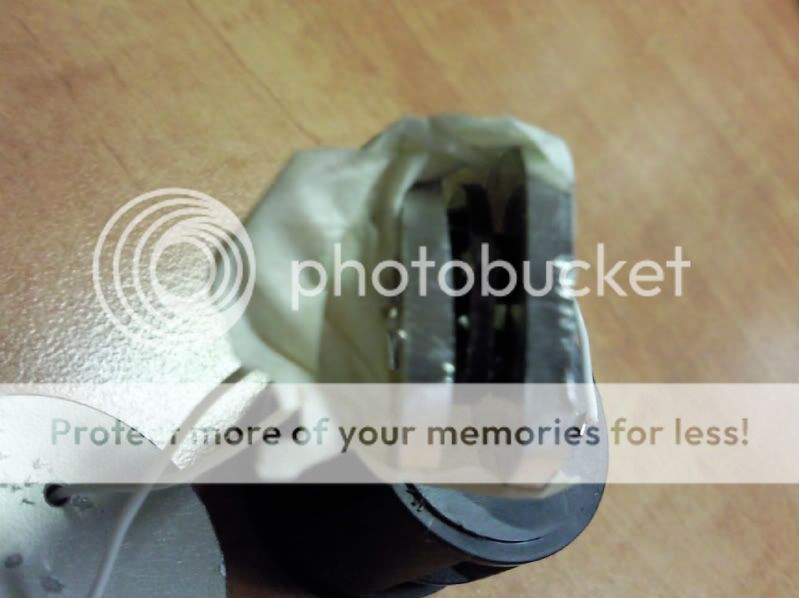
I've just mangled together 2 aluminum heatsink discs a little bigger than the diameter of a c cell and taped them tightly either side of the driver.
With 4 c cells the current held for a little longer then dropped again but slower.
The sinks got very hot too.
I've just mangled together 2 aluminum heatsink discs a little bigger than the diameter of a c cell and taped them tightly either side of the driver.
With 4 c cells the current held for a little longer then dropped again but slower.
The sinks got very hot too.
Vestureofblood, how you got two of these with a couple of sinks running amazes me.
Also I checked the soldering of the mounting tags.