Simple Standlight - Passive Components

kg6gfq

Newly Enlightened
Joined
Nov 9, 2015
Messages
14
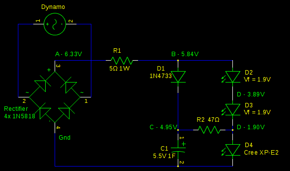
Well, I figured out the problem with D3 - I mis-measured it's Vf. After hooking it up to the fancy power supply at the local hackerspace this evening I found that it didn't start passing substantial current until 1.9 or 2.0V.

I also did a quick voltage-current graph for the B&M Lumotec IQ Fly Senso Plus headlight I'm using, driving it with a DC power supply:
fly senso plus graph.png


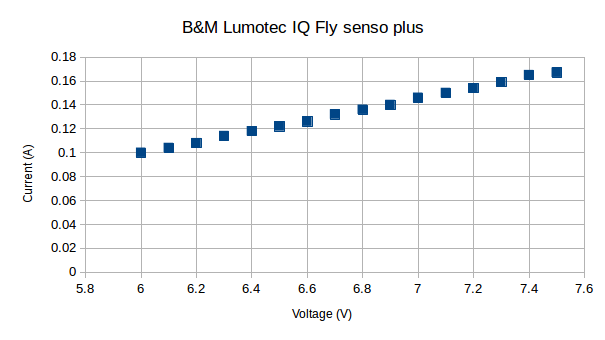
I also put the voltmeter on it while riding this evening and, while I could barely read the meter (it gets dark so early!), it looked like it was somewhere around 7V - consistent with the voltage I was seeing when running it with the taillight. Unless the light responds very differently to AC, that means it only needs a little over 100mA. I'm not clear how that works, given the dynamo is supposed to put out around 500mA. I'm not quite sure what that means for the taillight I'm working on, either.

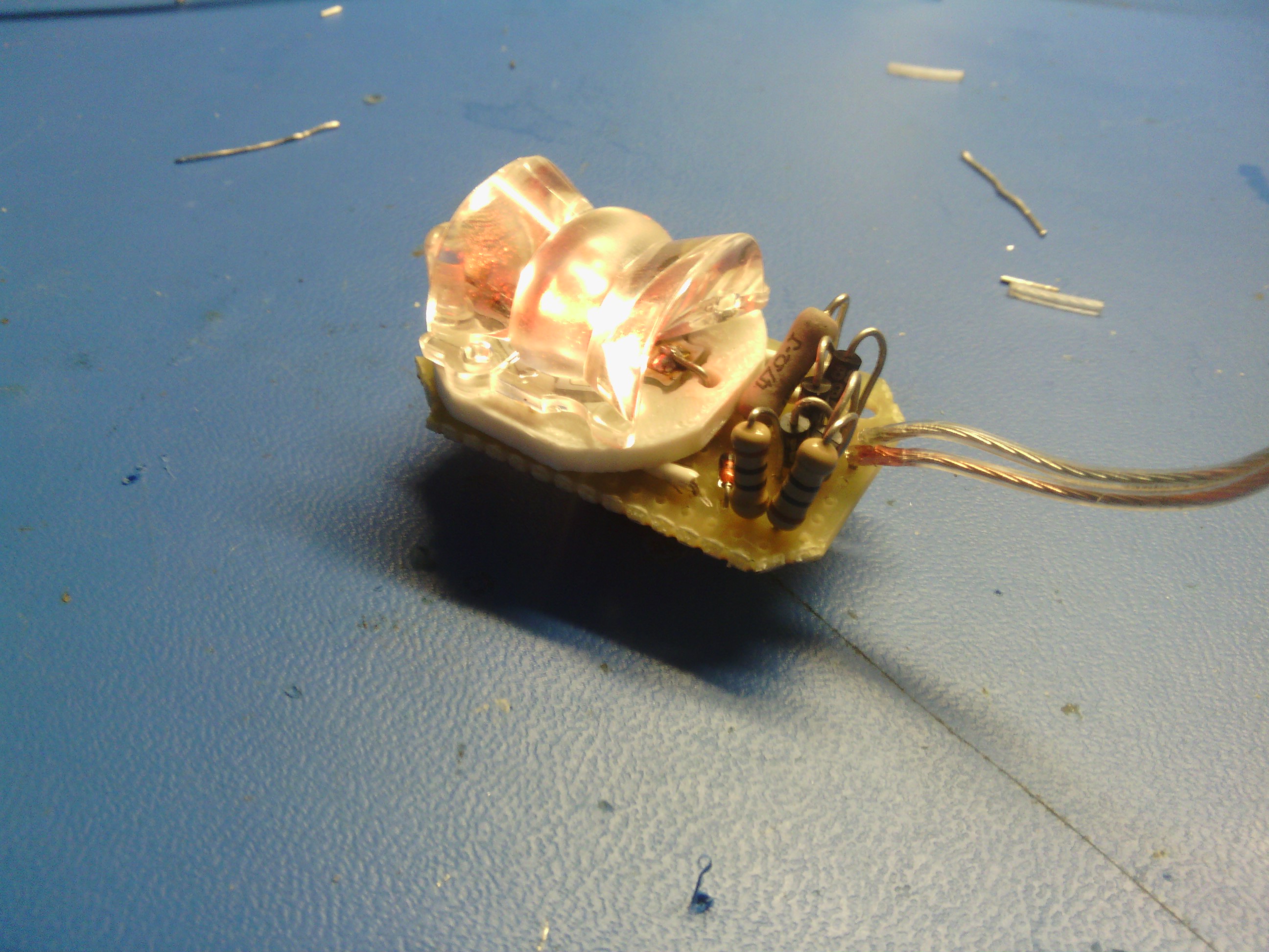
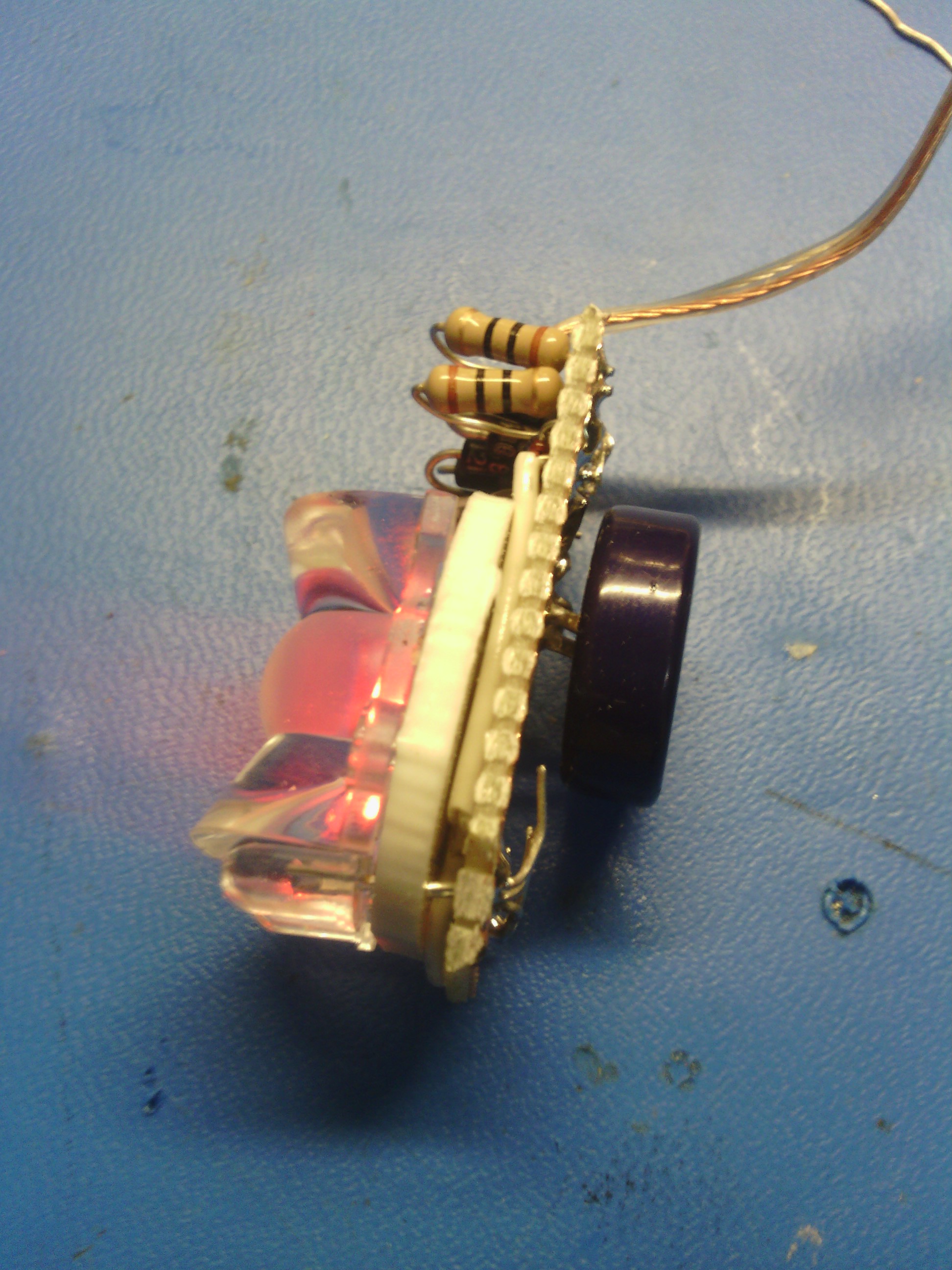
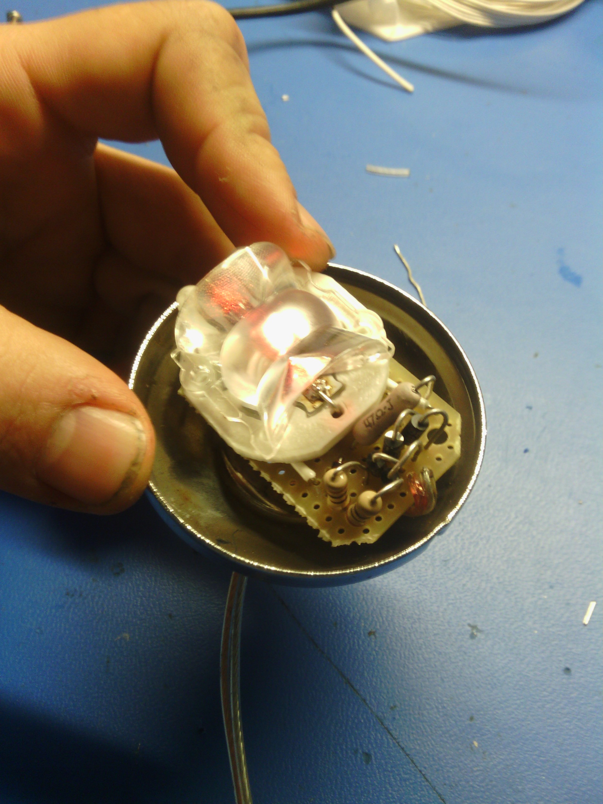
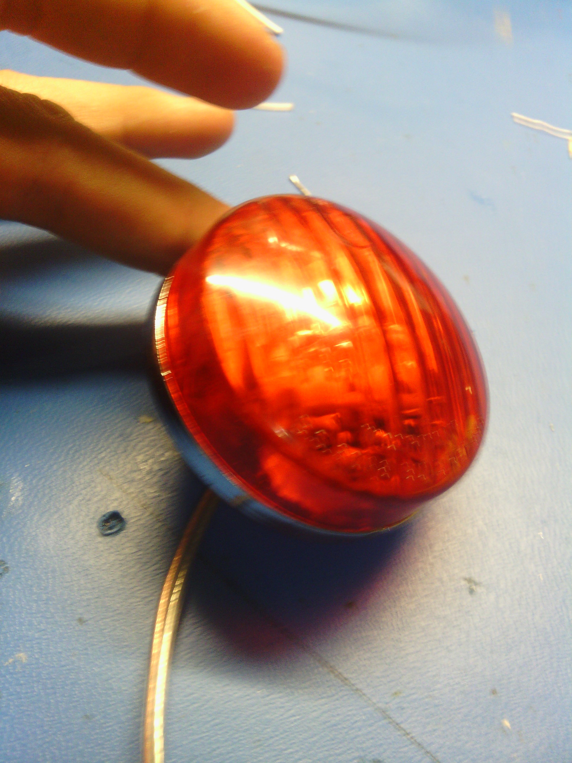
Speaking of the taillight, after a bit of tinkering with both lights hooked up to the fancy power supply I made a few changes. I'm going to hook the light up and test it out on the way home.

Savvas - the only powerLED is the one across the capacitor. I haven't noticed much dimming of the headlight, and given the chart above I doubt I ever will - this headlight seems to run at surprisingly low power. I wanted to use the XP-E2 so I could put the LEDiL "Flare" optic on it, which I quite like, but it doesn't last very long as a standlight, so I'm thinking about going back to the basic 5mm LEDs. I'd love to do some serious testing with the dynamo as a power source, but I haven't yet broken down and built a rig to drive the wheel while in a stand, so the only way I can do it is with the voltmeter on my handlebars, taking quick readings as I ride.
 

Steve K

Flashlight Enthusiast
Joined
Jun 10, 2002
Messages
2,786
Location
Peoria, IL
a response to the new component values... the info does make the data seem more appropriate. However, it still seems wrong/inappropriate that D3 should only be getting 5mA.

This is primarily due to R2 being so small. Using a small value for R2 effectively shorts around D3, letting almost all of the current get burned up in R2 instead of producing light in D3.

The low value of R2 also keeps the supercap from charging up very high. .. although increasing R2 won't make much difference. The low Vf for both LEDs means that the cap can't charge up beyond 3.7V. It might be worth adding a silicone diode in series with D3.

The low value for R2 means that the supercap discharges quickly. Using the equation I = C x dV/dt, where dV is the change in capacitor voltage and dt is the change in time, you can get an idea of how long the supercap can produce 65mA of current.

dt = C x dV/I , where C =1F, dV = (3.4v - 1.8)v, and I = 0.065A.
The value for dV is 3.4v - 2.0v because the initial voltage is 3.4V and the final voltage is 1.8 (which is forward voltage for D4). This gives a result of dt = 24.6 seconds, meaning that the standlight will run at 65mA for 24.6 seconds.
In the real world, the current will drop below 65mA pretty fast, and will still put a little current into the LED even when the supercap is below the nominal Vf.

Personally, I'd probably shoot for 30mA through D3, which would require that R2 be approximately 51 ohms.
 

kg6gfq

Newly Enlightened
Joined
Nov 9, 2015
Messages
14
Well, this is what I've been running for the past week or so:
simple_standlight_update2015.12.26.png


Voltages were taken with 7 VDC / 0.1A in place of the dynamo, and are pretty consistent with measurements taken on the bike, running from the hub dynamo. D1 is back to being a zener, but when riding fast I've measured point "C" at over 5V, so I think it's about right given the total drop across D2, D3, and D4.

The good news is that it's drawing about the current I was aiming for, and charging C1 quite high. The light is very bright when moving, and will probably work great with the Flare optic on D4.

The bad news is that standlight performance is still pretty poor, with the voltage at "D" dropping below 1.8V less than 30 seconds after power is removed. Swapping in a 2.2F capacitor for C1 more than doubles the runtime (as that handy equation of Steve's indicates), and I think it's adequate, but it's still not great. Also, driving the XP-E2 at higher current could give a good deal more light.

Conclusion: This is far from the best standlight circuit for a Power LED unless you use a larger supercapacitor. In fact, any parallel taillight using the XP-E2 will be tricky, since you'll presumably be wanting to give the headlight the lion's share of the current, leaving the taillight wallowing in the 0.1A range.

Potential improvements:
1) 2F (or larger) capacitor. It would work fine, but the larger-value caps are pretty bulky, and the XP-E2 will still be running at the low end of its power curve.

2) Series taillight. (so long as you don't care about compatibility with manufactured lights)

3) Don't use Power LEDs in the taillight - stick to 5mm LEDs and focus on using lots of them and/or creating optics that spread their light over a large area for visibility, like the Toplight Line series from B&M. (Anyone have tips for DIY optics?)

4) Active components - it seems like some combination of active switching, higher voltage capacitor, and maybe a buck converter would allow the XP-E2 to run at higher power AND give a better standlight duration. Or copy Steve and use a battery. (-:

Opinions welcome. For now, I'll probably solder this up and stick it in a housing, since it should serve pretty well until I can create something better.

Once again, thank you Steve and Savvas for all your help!

-Darin
 

Savvas

Enlightened
Joined
Jun 11, 2010
Messages
222
Darin,

Just food for thought - maybe. I have several times built a similar circuit for a headlight using 2 x XR-Es (that is where you have D2&3 and D4). It used a 1F Elna super cap and a 47 ohm bleed resistor to what you refer to as D4. No R1 and D1 was just an ordinary silicon diode. Big smoothing cap across the +ve and -ve buses just after the rectifier. I get maybe 5-10 minutes of quite acceptable stand light illumination from 'D4'. No parasitic tail light of course and current values are likely to be quite different. I guess my point is that the circuit can be effective using power LEDs.

However the headlight + tail light combination is a different kettle of fish of course. I suspect that further experimentation using standard 5mm LEDs (no power LED) might be worthwhile - I think this is what you are in fact suggesting above. Really, the only reason we need to use power LEDs in a dynamo stand light circuit is in the headlight (to see where we are going). Cateye have demonstrated long ago that 3-5 very efficient 5mm LEDs make perfectly acceptable rear 'be seen' lights (for night-time use anyway).

Thanks for this persisting with this experimentation - it's been interesting to follow. You've sort of continued on from where CPF's 'great stand light thread' petered out - I suspect because the original B&M Toplight proved so popular and effective at quite a cheap price point that further experimentation seemed a bit pointless! Well done!

Savvas.
 

Steve K

Flashlight Enthusiast
Joined
Jun 10, 2002
Messages
2,786
Location
Peoria, IL
.......
The good news is that it's drawing about the current I was aiming for, and charging C1 quite high. The light is very bright when moving, and will probably work great with the Flare optic on D4.

The bad news is that standlight performance is still pretty poor, with the voltage at "D" dropping below 1.8V less than 30 seconds after power is removed. Swapping in a 2.2F capacitor for C1 more than doubles the runtime (as that handy equation of Steve's indicates), and I think it's adequate, but it's still not great. Also, driving the XP-E2 at higher current could give a good deal more light.

Conclusion: This is far from the best standlight circuit for a Power LED unless you use a larger supercapacitor. In fact, any parallel taillight using the XP-E2 will be tricky, since you'll presumably be wanting to give the headlight the lion's share of the current, leaving the taillight wallowing in the 0.1A range.

Potential improvements:
1) 2F (or larger) capacitor. It would work fine, but the larger-value caps are pretty bulky, and the XP-E2 will still be running at the low end of its power curve.

2) Series taillight. (so long as you don't care about compatibility with manufactured lights)

3) Don't use Power LEDs in the taillight - stick to 5mm LEDs and focus on using lots of them and/or creating optics that spread their light over a large area for visibility, like the Toplight Line series from B&M. (Anyone have tips for DIY optics?)

4) Active components - it seems like some combination of active switching, higher voltage capacitor, and maybe a buck converter would allow the XP-E2 to run at higher power AND give a better standlight duration. Or copy Steve and use a battery. (-:

Opinions welcome. For now, I'll probably solder this up and stick it in a housing, since it should serve pretty well until I can create something better.

Once again, thank you Steve and Savvas for all your help!

-Darin

Glad to hear that progress has been made and lessons have been learned!

It's not easy to start from scratch (i.e. zero experience) and come up with the perfect standlight circuit for your needs. It takes time to figure out exactly what you want from a standlight, even if other people say that one circuit is great and another circuit is no good.

Once you've got some idea of how much light you want the standlight to create and how long you want it to run, you can use the basic equations to calculate how much energy needs to be stored. For quick review, Power = volts x amps, where power is in units of watts. Energy is equal to power times time, where watts = joules/second, where the joule is a unit of energy.

The energy stored in a capacitor is 0.5 x C x V^2, i.e. one half the capacitance times the square of the voltage that the capacitor is charged to. Due to the limitations of the load, whether it is just the LED being powered, or a boost converter powered by the capacitor, the capacitor can only be discharged to some low voltage, so don't forget to consider how much power will be left unused in the capacitor.

Anyway.... once you have an idea of how much power and run time you want/need, it's useful to run the calculations and see how much capacitance and voltage you'll need. It beats buying part and building circuits over and over! :)

I'd suggest using this circuit for a while and seeing if you are happy with it or not. Your experience will probably influence what improvements you'll want in the next design, if there is one.

Regarding the list of potential improvements...

1. larger super-caps: I'd say use the biggest cap you have room for. Use a good grade of cap too, with lower internal resistance.

2. series taillight: as noted, it's not clear how well this will work with modern LED headlights that may not pass 0.5A through it. You may have to look at the voltage-current relationship of your headlight and see what the optimal taillight design would be. Maybe it's a parallel taillight that would be allowed to draw more than the nominal 100mA??

3. don't use power LEDs: I'm not sure why this would help. They should be as efficient as the 5mm LEDs. Or is this just a question of the associated optics? 5mm LEDs give you the option of choosing ones with narrow beams and then aiming them in the desired directions.

4. active components: these add cost and complexity and use more board space, but can make better use of the energy stored in the supercap. For the novice, perhaps there's a commercially built driver that would be the equivalent of the little Zetex boost circuit that I use?
 

Savvas

Enlightened
Joined
Jun 11, 2010
Messages
222
3. don't use power LEDs: I'm not sure why this would help. They should be as efficient as the 5mm LEDs...

Steve,

In suggesting further research using only standard 5mm 'non-power' LEDs, I was just thinking of the short stand-light run time Darin was seeing and a possible relationship to the current requirements of a power-LED (as opposed to 2-3 standard 5mm LEDs in parallel).

Another line of enquiry maybe worth pursuing might be to reverse the arrangement of LEDs in his current circuit and use the standard 5mm devices for the stand light. Would not the lower current they require lead to longer run times from the cap?

My reference to Cateye was simply to point out that, despite the move by many manufacturers to using 0.5W and 1W LEDs in battery-powered tail lights, there are still several Cateye designs that make excellent use of 3-5 x '20ma' LEDs with very acceptable results. I'm imagining that light outputs similar to some of these less powerful Cateye (and similar) tail lights would be very acceptable in the esoteric world of DIY stand-light design - no?

Savvas.
 

Steve K

Flashlight Enthusiast
Joined
Jun 10, 2002
Messages
2,786
Location
Peoria, IL
Sam, you use the phrase "the current requirements of a power LED"... but I'm not sure that I'm interpreting it the same way that you are.

Power LEDs are different from 5mm LEDs in that the die is larger and there is usually better heatsinking possible. The power LEDs tend to not have any attached optics. They don't have any particular current requirements.. but they do have a larger limit on the applied current. They will work quite well on very small currents.

In my latest headlight, a supercap is used to power the boost converter, which drives one of the two 3W LEDs. The supercap only charges to 2.5V, but this is enough to forward bias the LED and a schottky diode at low currents. The small current from the supercap is enough to make the LED glow quite visibly and takes a day or two before it is too dim to be visible in room light.

It's hard to get comparable data on 5mm LEDs vs power LEDs. This probably due to the integrated optics on 5mm LEDs vs no optics on power LEDs. My modest experience is that the two are roughly comparable for a given amount of current.
 

kg6gfq

Newly Enlightened
Joined
Nov 9, 2015
Messages
14
It's hard to get comparable data on 5mm LEDs vs power LEDs. This probably due to the integrated optics on 5mm LEDs vs no optics on power LEDs. My modest experience is that the two are roughly comparable for a given amount of current.

Interesting - I had the impression that 5mm LEDs produced noticeable light at substantially lower current than power LEDs. That could be a result of the integrated optics, though, or just that I haven't spent much time observing the two with that comparison in mind.
 

Savvas

Enlightened
Joined
Jun 11, 2010
Messages
222
Hi Steve,
I guess I was thinking that a powerLED in the stand light part of the circuit would sink the available current faster and hence lead to a shorter run-time from the limited charge available. But now I consider it more, I realise that - other things being equal ('bleed' resistor value, voltage drop etc) - this doesn't make sense and just represents my persistently limited understanding of these things. If a power-LED will operate at low current levels like the 20ma limit of the 5mm LED and produce usable light, then there's probably no real electrical advantage in using the smaller component.
In a PM to Darin I have remarked that messing about with LEDs keeps the brain cells ticking over. Not sure if this is really true in my case... ;-)
Sam
 

kg6gfq

Newly Enlightened
Joined
Nov 9, 2015
Messages
14
1. larger super-caps: I'd say use the biggest cap you have room for. Use a good grade of cap too, with lower internal resistance.

A higher ESR will result in slower charge/discharge of the capacitor, correct? Are there any other potential disadvantages?
 

Steve K

Flashlight Enthusiast
Joined
Jun 10, 2002
Messages
2,786
Location
Peoria, IL
A higher ESR will result in slower charge/discharge of the capacitor, correct? Are there any other potential disadvantages?

It does slow the charge and discharge, as noted. Since some circuits, such as this one, add a resistor in the discharge path to slow the discharge, the slower charge rate might be the only disadvantage (and even then, there might be an advantage in a slower charge rate).

The ESR also wasted power when charging and discharging. Whether or not this is a concern depends on the circuit design and the performance requirements. You'll spend more money on a low ESR cap. As in many engineering disciplines, the trick is to get performance that matches the requirements for the least amount of money/weight/size/etc. For a hobbyist, cost may not be that big of a factor compared to the time and effort invested in the device.
 

kg6gfq

Newly Enlightened
Joined
Nov 9, 2015
Messages
14
Well, here's the finished circuit all soldered up:
board_front.jpg


Side view shows a 1F capacitor on the back - the 2F was just too bulky:
board_side.jpg


The LED and lens are held in place by a 3D-printed backing plate. I forgot to get a photo of the final print, but this test print gives a pretty good idea of the shape:
led_holder.jpg


With a little trimming, I was able to fit the board into an old Union dynamo taillight:
board_inhousing.jpg


And the whole thing looks like this:
complete.jpg


The Union lens breaks up the beam from the flare optic. Pointed at the wall, it looks like this:
light_onwall.jpg


Not my favorite beam pattern, but it's not bad - and I'm pleased to have a taillight! The only thing left is creating a 3D-printed part that will attach to the back of the light and fit the mounting bracket on my rear rack.

Steve and Savvas, thanks again for all your help!

-Darin
 

Savvas

Enlightened
Joined
Jun 11, 2010
Messages
222
Looks v/nice and neat. Did you end up using the circuit in post #23? Have you tried the light with just the flare optic - without the Union enclosure? Union also made a nice stainless steel rear light with a domed, non-ribbed enclosure which may be worth trying (if you want an enclosure that is).

Savvas.
 

Steve K

Flashlight Enthusiast
Joined
Jun 10, 2002
Messages
2,786
Location
Peoria, IL
good to hear that it is working!

I'm accustomed to using surface mount parts, so seeing the leaded resistors and stuff is a visual shock to me, but if it fits and it works, it is good enough! I do worry a bit about parts vibrating and the leads bumping into each other and causing shorts. Some RTV or Plasti-Dip will hold things in place and insulate the leads at the same time.

Combining the optics that you want, and the optics built into an old housing can produce undesired results. You might see if you can find a flat piece of red plastic that could be used to replace some of the Union light's lens. Seems like a lot of work for a small improvement. I'd say to use it as is and see how you like it (which was probably already your plan).

Have fun with the light and casually tell your friends that you made it yourself (while smiling smugly!). :)
 

kg6gfq

Newly Enlightened
Joined
Nov 9, 2015
Messages
14
Yep, the circuit is the one from Post #23.

I'll have to wait and see if vibration is a problem. I don't know that I have the soldering skill for delicate SMD work yet, but it sure would be nice for compactness.

The Union lens is just what I found at the local Bike Collective, and it's much easier than making a new housing from scratch! I've tried the Flare optic alone and it gives a nice even beam about 100* along the horizontal axis, and vertical compression similar to what that photo shows.

Looking at the plain Flare optic, the light appears to be a small vertical line. Looking at it through the Union optic, there are several vertical lines from the different ribs - almost like the idea behind the B&M Line series, so maybe it's a good thing.

Of course, now the bike it's going on is out of commission until I build a rear wheel with a better hub - the current hub has severe water-infiltration issues. Always another project... (-:

-Darin
 
Top