WTB: machining/lathe services

StrayLight

Enlightened
Joined
Oct 4, 2007
Messages
667
Location
Saint Louis
Originally posted in B/S/T with some good brainstorming from Mirage Man and Morelite, but my request to have the thread moved to Machining subforum was ignored, so it's closed and here's a new one with the same info...

I would like to have my McGizmo Cx2 titanium body (first photo below) bored slightly to accommodate AW protected 17670 rechargeable cells. I have four cells and, because of the variations in thickness/placement of the protection circuit and shrinkwrap, only one fits (and snugly). I think less than 1/16" total material removed would be necessary.

McLuxIII titanium Cx2 with S27 head
Rust-1.jpg


E-series 2x123 titanium McClicky body, better view of OD and profile but threaded differently to fit Aleph & E-series heads
2x123Packs.jpg


Many modders and builders here are likely set up for this kind of work, but I have no idea what's needed to do this properly (if at all).

Thanks for looking.
 
Many modders and builders here are likely set up for this kind of work
There's probably someone with the correct reamer, but this would be a tough job to bore. The outside diameter of a CR-123 cell is 17mm, and length is 35 mm. The boring bar has to extend 70+ mm to reach the bottom of the battery tube. Even a solid carbide bar will have a tough time reaching that far and maintaining correct diameter in Ti-6-4.

A reamer is the way to do this job, either 17.5 mm or 18 mm. If I had one, I'd do it for you. Someone here probably does.
 
I have an 18mm reamer, but that o-ring gland makes me nervous. That area probably has the smallest OD. If there is any way you can remove the o-ring and measure that section with calipers (I think that any machine shop would measure this for you for free), we can determine if what you want is possible. Maybe you can get that info from Don.
 
I posted a thread a few days ago about battery tube reamer sizes. No one was interested in discussion.

Would 18mm be the optimum reamer size? What about 45/64? That's a bit smaller than 18mm but should still allow any 17670 to fit and may make up for the OD of the O-ring gland. Is that what it's called? An "O-ring gland"?

I've been wanting to order some battery tube reamers, but not sure what sizes to order.
 
It's probably a good idea to measure it anyways. Part-to-part variation has been my downfall on more than one occasion.
 
Thanks for the suggestions. I don't have calipers, so I'll have to search out a machine shop.

Point of reference, I have the light in the top photo, with internal threads where the head attaches. I posted the second pic because, while the threaded portion is different, it better shows the overall design and profile of the body. And it's not an illusion... the OD of the ribs gets slightly larger at the center.
 
I posted a thread a few days ago about battery tube reamer sizes. No one was interested in discussion.

Would 18mm be the optimum reamer size? What about 45/64? That's a bit smaller than 18mm but should still allow any 17670 to fit and may make up for the OD of the O-ring gland. Is that what it's called? An "O-ring gland"?

I've been wanting to order some battery tube reamers, but not sure what sizes to order.

It's not that it was not worth discussing. There are standards for many commercial batteries and you can look some of them up at http://www.duracell.com/oem/productdata/default.asp

The nominal size of a 17670 is 17mm diameter. The size of the protection circuit and shrink wrap are anyone's guess. :) That's why you are not getting a lot of absolute responses.


Daniel
 
It's not that it was not worth discussing. There are standards for many commercial batteries and you can look some of them up at http://www.duracell.com/oem/productdata/default.asp

I'm not having any trouble finding dimensions of batteries. I want to know what size reamers to buy. I figured there was some standard, I guess I was wrong. If you bore it too small not all protected batteries will fit, if you bore it too large, batteries will rattle around inside the tube.


The nominal size of a 17670 is 17mm diameter. The size of the protection circuit and shrink wrap are anyone's guess. :) That's why you are not getting a lot of absolute responses.
Daniel

Right, but people must be boring battery tubes to some dimension. I wasn't necessarily looking for absolute responses. I really just needed some advice. Reamers are not cheap, so I wanted to make sure I was buying the most appropriate sizes.


Anyway back on topic, does anyone know which is more appropriate for 17670 18mm or 45/64?
 
18mm for an e-series body is too much IMHO, the top oring groove limits what you can and what you can't do. I would go with 17.5 or 17.6mm tops

From a CAD drawing of mine, here is a cut view of the top part of an E-Series body:

eseriestoporing.jpg


that measurement varies a little from manufacturer to manufacturer, mostly to make the oring seal more or less compressed.

I use an AW 17670 on one of my pineapple bodies on a daily basis without a problem.

Pablo
 
Thanks for the continued input, but to clarify my original request: the body in question is not E-series, but McLuxIII with threads internal to the body.
 
Have you tried sending a PM to McGizmo? If someone knows if it can be done safely is definetly him.

AlexGT
 
......... If there is any way you can remove the o-ring and measure that section with calipers (I think that any machine shop would measure this for you for free), we can determine if what you want is possible.

This is the only way to find out if there is enough wall thickness.That 'O' ring grove is where there might be a problem. No machinist
worth his salt would attempt this without knowing exactly how much metal he has to work with. Also one has to be able to grip the workpiece and make sure it does not turn through the reaming or boring operation.
 
........and to make maters worse.

Carefully look at the photos supplied above by the OP.
It looks to me that the body is barrel shaped and this will cause more problems when attempting to hold it securely without damage.

I think the best thing is to power hone it with a 3 finger auto brake hone.
Messy, much patience required, but if done by the OP, the minimum metal can be removed and trial fit is possible.

Or one could use a flap wheel on a shaft extension .See link
http://www.restockit.com/2-1-2-x-1-...e=froogle&Bvar5=100F1&Bvar6=100F1&Bvar7=100F1
 
Last edited:
Thanks for the continued input, but to clarify my original request: the body in question is not E-series, but McLuxIII with threads internal to the body.

I caught this thread the other day and realized that you were not seeking to open the bore of an E-series which would be a problem because of the O-ring groove (.750" OD at root) VS the ID of the tube which is nominally .675" leaving you with a wall thickness of .0375" before you remove any material.

Since you want to bore out the Cx2 pak, your minimum wall thickness will be at the root of the grooves on the body itself which is about .780" OD so at present, you have a wall thickness of .0525". You can determine the resulting wall thickness after the boring out and decide if this is acceptable to you. It is all straight forward to my way of thinking and since I have no intention of offering or attempting such a mod, I refrained from posting. Had you been wanting to open the bore on the 2x123 McClickie pak, I would have posted in a cautionary, "Don't Do It" and why. Your "less than 1/16" material removal" was not specific enough for me to make a judgment call but now that I am posting, I would advise that it would be best if it is well bellow 1/16". If you remove .0625" of material, that will leave you with minimum wall thickness of ~.022" which is viable considering the tube is Ti but the light will appear to be much more robust than it actually is. The part could also act up on the machinist in the process of removing this material!

Don apparently doesn't keep very good records. In the past when I've asked technical questions, he has been quite vague with the details.

I don't doubt that I can be vague on details depending on what the question was and how old it was in reference to. I have hundreds of drawings going back many years and my memory is the pits. Without knowing the reference, I won't attempt a guess at what this is or was about. I may well have been vague for other reasons as well. :shrug:

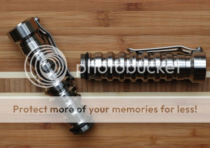
As you and others have identified, the profile of the pak has a curved outer form and each rib is different in OD. I would imagine that a pressed on sleeve in say delrin that had an OD to match that of the tail OD might give you a good a reasonable grab on the pak.

Last night I saw your request for

..exact dimensional drawing of the McLuxIII Ti Cx2 Clicky Pak
I figured I would sleep on a response as my initial response was one of surprise and incredulity. I don't even have an exact dimensioned drawing on this part because I was able to supply it in an IGIS file to the machine shop and they pulled what dimensions they wished from the solids file. Now I could take an hour and generate a dimensioned drawing and convert it to PDF but frankly, why should I?

It has been my experience that if I plan to modify a specific part then I use that part to provide me the geometry I am working with; especially if I plan to push it to its limits. Because there are tolerances involved in the general case, I am more interested in the actual dimensions of that which I am modifying.

Years back, I decided to base much of my design on the "E" series of SureFire. I gleaned from PK that he had no real problem with this. I never asked him for SF drawings, critical or target dimensions with tolerances or any other questions regarding their design. I figured if I wanted to use their dimensions that it was up to me to glean them from parts on hand. :shrug:

I have seen some of my stuff reverse engineered and in some cases, I could care less and in others, I feel that the work was a bit too close to my home and I won't make a stink about it but I certainly didn't appreciate it. At any rate, I have no interest in making it easier for someone by providing exact dimensioned drawings!

To be clear here, I see no problem or issue from my stand point in you seeking to modify your battery pak to be host to a battery it was not intended for. To my perception, the critical dimensions are existing bore and intended bore and how they relate to the material at hand. In addition you need to deal with a part that does not have a consistant OD across its length.

Had I intended for this pak to host a larger diameter battery, I would have designed it that way and not gone as deep with the rib groves.

You want to modify it which is your call and I hope my comments specific to this modification have been of some assistance. With a pair of digital callipers, I believe you could have determined the needed information in a matter of moments, yourself. I don't doubt there is talent here and some machinists who can accomplish what you seek. I don't see this as a trivial modification but that is based on my personal experience; as limited as it is.
 
Don,

I've obviously touched a sore spot here, but that was not my intention.

I've found a light profile I really like in the LunaSol27, and improved ergonomics in using it with the Cx2 Pak, but the Cx2 doesn't consistently accommodate my intended rechargeable cells and the LS27 cannot be run on two primaries. To solve this dilemma for my own personal use is the sum total of my intention behind inquiring about modding the Cx2.

I first asked here among the modding community at large because:
1) I thought someone would have had experience with this light and possibly contemplated this work already, and
2) my aforementioned remark about your record keeping and sometimes vague responses to questions.

You apparently have your reasons for being intentionally vague, which I don't claim to entirely understand, and you have written on more than a couple occasions to not keep certain records, so some questions (in my case IIRC relating to input voltage for a particular converter) have received vague answers for lack of archived information.

Naturally, I was directed back to ask you for some specifics about the Cx2 to help determine if this mod is possible. That you read my identical thread on B/S/T and consciously chose not to respond because it didn't benefit you leaves me with a feeling of incredulity, and only serves to reinforce my comment about being vague, just for entirely different reasons.

In the end, I feel scolded for even asking. I don't have the technical expertise or equipment to tackle this project. I don't have calipers, digital or otherwise, with which to take measurements myself, and not a lot of time to truck this around locally to find someone who does. I could just ship it to a modder here, but I'd like to know before laying out that expense if this work is physically possible.

So I asked the experts in our community for input. They told me to ask you. While I suppose the way I phrased "dimensional drawing" apparently raised a red flag, I hope it's obvious that I have no intention (or ability) to poach or profit by asking these questions.

So, that being said, thank you for the measurements. Though I may need to get this directly in the hands of one of our machinists here, the ID and root OD may be enough to determine feasibility.
 
It's probably within .004" ~ .006" for a good fit, with all of your AW 17670 cells.

A 3/8" carbide shank boring bar will work fine, even with the long (boring bar) extension ratio that cell body would require for boring.

If one or both of the center ribs is the same diameter as the tail end of the cell tube, chucking the body shouldn't pose any obstacles.
 
...
If one or both of the center ribs is the same diameter as the tail end of the cell tube, chucking the body shouldn't pose any obstacles.

Unfortunately, the tail end is larger in diameter.

StrayLight,

Naturally, I was directed back to ask you for some specifics about the Cx2 to help determine if this mod is possible. That you read my identical thread on B/S/T and consciously chose not to respond because it didn't benefit you leaves me with a feeling of incredulity, and only serves to reinforce my comment about being vague, just for entirely different reasons.
I answered poorly in my comment about electing not to post. Initially I had a post going about the problem of wall thickness and then realized your pak has the female end and that what you seek is possible. Your post here is about wanting to buy machining/ lathe services. I am not selling these so no need for me to add clutter to your thread. There would be no benefit to YOU in a post contribution from me. I have not followed the thread since until I saw your post in the McGizmo forum last night asking for an exact dimensioned drawing of the pak. This morning, I decided to find this thread and see what had transpired. I find that you have little suspicion that I will be of any help because I am vague and poor in record keeping (Unqualified guilt admitted on the latter point). If you want to take me to task on points where Ihave been vague, it's your perogative. The less vague you are in identifying those points, the more likely a reason or justification might be offered up. No doubt a waste of your time and my time. Heck, I am basically a jerk but if I can keep from imparting that to my lights then they won't be so encumbered or flawed (hopefully). If you hit on a sore spot, it isn't a spot that you made sore and sorry for comming down on you, if I did.

I understand your goal here and it is a reasonable one. I understand that you have no desire to poach or profit on any of this information. The parts can and have been properly reverse enginered without aid of detailed drawings but I have no interest in making it any easier for those who would be inclined to poach or profit on my designs. No harm and no foul on your part.

I personally find it very frustrating that these 17670 batteries won't fit! You don't seem to have a target bore diameter identified yet or perhaps I have missed it. Without knowing what the bore needs to be, how can you proceed? 17 mm is .669" so "on paper" a bore of .675" should be a nice snug fit! If you are going to identify the diameter of something and there is any consideration that that thing might be going into something else, it makes sense that the identified diameter is a maximum. What the hell is the diameter of a 17670 battery?!?!

Your quest for a machinist to bore out your battery tube has given me the opportunity to spend an hour or two in contemplation and composition as well as demonstrate that I can be vague and a bascially a jerk. Beyond that, I don't see any gain here for any of us. :nana:
 
What the hell is the diameter of a 17670 battery?!?!

Therein lies the problem:devil:

If you know that you'll only use a particular cell from one manufacturer, buy a representative sample and measure the diameter of each one ... a 0-1" micrometer is better for this than a digital caliper or dial caliper, and you can find a decent 0-1 mic on eBay for under $20, delivered. The problem is not so much what you use to measure, as it is the possible cell to cell variation in diameter. I don't know where AW (for instance) sources his cells, but they are manufactured to a target diameter of .xxx", and there's a tolerance above & below that dimension that is still acceptable - the reason for the +/- figure on most prints. You need to determine the largest size that will be encountered & add enough wiggle room to allow the battery to go in or out without force. 0.678" that TB mentioned sounds like a workable number.

If someone is ready & willing to do this for you, they haven't yet posted that offer. One reason is that the body will require a custom fixture. If I had to build that, I'd bore a length of solid round so that the ID matched the OD at the tail & head of the body, then split the bored sleeve, then drill & tap clamping bolts located at both ends ... most shops would price that somewhere north of $100, without counting the labor to bore or ream the body.

I don't see this as a trivial modification
+1

I'd price that as:

Fixture cost + reamer cost + labor cost + cost of one replacement tube, as there's a high probability that it won't turn out right the first time around:shakehead
 

Latest posts

Top