LEDs wired in parallel, issues with different Vf?

Hirudin

Newly Enlightened
Joined
Sep 5, 2004
Messages
26
I'm planning to build a large RGB array using Luxeon Rebels and the CCHIPO driver. Currently I'm planning to have 28 sets of LEDs.

By the looks of it, the blue LEDs should be run at 385 mA, which will make their typical Vf 3.2.

The CCHIPO driver has an output limit of 39 V and 45 W. So, if wired in series I'll be limited to 12 LEDs (3.2 V * 12 = 38.4 V). But this will only be using 14.784 W (38.4 V * 385 mA = 14.784 W); well bellow the CCHIPO's 45 W limit.

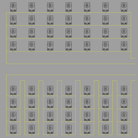
It seems to me that I could run 7 sets of 4 parallel wired blue LEDs in series (like the image at the bottom). The way I see it, each set of parallel LEDs should have a Vf of 3.2 and 1.54 A. All 7 sets would have a total Vf of 22.4 and 1.54 A for a total of 34.496 W.
22.4 V and 34.496 W are both well bellow CCHIPO's limits.

bluearray.gif


The problem is, I wont be able to get binned LEDs, so the exact Vf of each LED will be unknown. Also I've heard that the Vf will change over the life of the LED and will also change when the bulb warms up.

What issues are there with wiring LEDs with different Vfs in parallel?
 

greg_in_canada

Flashlight Enthusiast
Joined
Jun 7, 2004
Messages
1,146
Location
Saskatoon SK Canada
You risk current hogging on the branches with lower Vf_total and in the worst case thermal run-away where the low Vf branch hogs more current, gets warmer than the other branches, Vf gets lower, hogs even more current, etc.

You could put something like a 1 or 2 ohm resistor on each branch. That would help even out the current sharing and help prevent run-away. Each 1 ohm resistor would waste about 0.15 watts so you'd want to use a 1/2 watt resistor to have a bit of safety margin. If you go with 2 ohms use 1 watt resistors. Using even higher resistances will keep the current balanced even better, at the cost of more power dissipation.

Greg
 

Hirudin

Newly Enlightened
Joined
Sep 5, 2004
Messages
26
Thanks greg_in_canada! I don't know much of anything about resisters, but I'll try not to be a typical newbie and go research them myself...

These LEDs are going into a planned projector, so even/balanced brightness is important. So, what you're suggesting is to use the highest ohm resisters that I can, so long as I have the wattage to spare, right?

I get into a "thermal run-away" situation does it eventually level out? What I mean is, when you said "etc." are you saying that the cycle of: Vf gets lower, hogs more current will continue until an LED is destroyed or something?
 

Hirudin

Newly Enlightened
Joined
Sep 5, 2004
Messages
26
I asked a very similar question here:
https://www.candlepowerforums.com/posts/2282936
Some good advice there (if you ignore some irrelevant interuptions! ;-)), and some circuitry which you migth be able to adapt to your needs.
Thanks Mash! I'd skimmed through that already, but I'm so green with electronics that a lot of it was over my head. Maybe that chip (the LM317) will work for both regulating/evening each leg like I want AND keep the other legs protected should an LED fail as you want? I'll have to look harder at those chips before buying anything...

I also thought it was odd that some people didn't want to stay on topic, 'tis the nature of forums I guess. :)
 

Mash

Enlightened
Joined
Dec 18, 2006
Messages
378
No probs!
I was very wary of extra bits and bobs and especially circuits to begin with as well. However messing around with an LM and one resistor is execptionally easy, there really is nothing to it. So you can just put an LM limited to your desired current on each leg and be safe!
On another point:
Im being stupid but I cant get my head round your diagram (is that 7x4 or 4x7)!


(just deleted lots of unnecessary calculations here!:candle:):

If we are both talking about the 4 legs of 7 in series (xitanium datasheet diagrams are cool in this instance), your calculations seem correct. Given the proviso that you SET the TOTAL output current at 1.54A (to be distributed to 4 legs!!!) using the resistor setting formula on the driver data page.
 
Last edited:

Hirudin

Newly Enlightened
Joined
Sep 5, 2004
Messages
26
...
On another point:
Im being stupid but I cant get my head round your diagram (is that 7x4 or 4x7)!
...
I don't know which it would be called. What I was going for is 7 sets ("legs") of 4 parallel wired LEDs each.

By my understanding to calculate the power requirements of LEDs wired in parallel you add the the currents together because all the LEDs get the same Voltage. For series LEDs they all get the same current but the voltage increases for each LED.

So each leg is 4 parallel wired LEDs that need 3.2 Vf and .385 A each. Add the current together but keep the same Vf and you get 1.54 A (0.385 A * 4) at 3.2 Vf. Then with all the legs wired in series you add up all the Vfs but the current stays the same, so that's 1.54 A at 22.4 Vf (3.2 Vf * 7).

These calculations could easily be wrong... if anyone can confirm or reject them please do!
 

Mash

Enlightened
Joined
Dec 18, 2006
Messages
378
I think you got it the other way around, or maybe I am reading your explanation wrongly!
Have you looked at the xitanium data sheet diagrams? they do a good job at showing it.
My suggestion is this:

1.54A 22.4V Total output
psu +ve -----------------------------
1 2 3 4
LED LED LED LED
l l l l
LED LED LED LED
l l l l
LED LED LED LED
l l l l
LED LED LED LED
l l l l
LED LED LED LED
l l l l
LED LED LED LED
l l l l
LED LED LED LED
l l l l
-ve -----------------------------------------​
I hope you get my gist, for some reason the forum is eating my spaces (why?), and refuses to let me use tabs (WYSIWYG my foot:naughty: )!
THis way legs 1 2 3 4 each get 385mA, ie the 1.54A gets distributed evenly between them, and each leg is at 22.4V.

Do I make sense?:)

PS look at this page, especially the last diagram.
 
Last edited:

Hirudin

Newly Enlightened
Joined
Sep 5, 2004
Messages
26
I think your spaces are disappearing because of the design of HTML. Multiple spaces are always converted to a single space in HTML. To make your chart look right you can wrap it in "code" tags, like this...
Code:
Lets say these LEDs have a Vf of 3.5 and require 500 mA

(+)--0--0--0---
              |
              |     (Series = same current)
              |
(-)------------

This array will need a 10.5 V power supply putting out 500 mA

========================================================

(+)------------
      |   |   |
      0   0   0    (Parallel = same voltage)
      |   |   |
(-)------------

This array will need a 3.5 V power supply putting out 1500 mA

I'm basing my calculations on these pages...
LED Circuitry Tutorial
and
Series and Parallel Connections


Hmmm... I think it's possible the voltage and amperage would be the same whether you have 4*(7S) or 7*(4P).
 
Last edited:

Mash

Enlightened
Joined
Dec 18, 2006
Messages
378
Thank you sir!, lets try!
Code:
[FONT="Fixedsys"]

psu +ve ----------------------------------------------------
1.54A	1		2		3		4
22.4V	LED		LED		LED		LED
	l 385mA		l		l		l
	LED		LED		LED		LED
	l		l385mA		l		l
	LED		LED		LED		LED
	l		l		l 385mA		l
	LED		LED		LED		LED
	l		l		l		l
	LED		LED		LED		LED
	l		l		l		l
	LED		LED		LED		LED
	l		l		l		l 385mA
	LED		LED		LED		LED
	l		l		l		l
-ve    --------------------------------------------------[/FONT]
 

Hirudin

Newly Enlightened
Joined
Sep 5, 2004
Messages
26
Yup, we were both right regarding the math. Both come out to a total of 1.54 A and 22.4 V.

I wonder if one way is better than the other.
Screenshot - 1_7_2008 , 7_38_08 PM.png


Does your way require less resisters/LM317s? I think so... Yeah, that needs 4 instead of 7.

Are there other advantages too?
 

greg_in_canada

Flashlight Enthusiast
Joined
Jun 7, 2004
Messages
1,146
Location
Saskatoon SK Canada
Yes the higher the resistance you can put in each branch the closer the currents will match.

If the LED branches were on different heatsinks I think you could get the lowest branch hogging most of the current (say 50% instead of the 25% it should). I don't know the "dynamic resistance*" of these LEDs so it's hard to calculate how imbalanced they can get. If they are all sharing a heatsink then the imbalance will be less (i.e. it won't increase until one branch destroys itself).

* the dynamic resistance is a simplistic way to model the LED voltage versus current curve: e.g. you have a perfect diode with (say) 3.2V drop and have a dynamic resistance of (say) 5 ohms. Then at 400mA the LED Vf would be 3.4V (= 3.2 + 5*0.4), at 1A it would be 3.7V (= 3.2 + 5*1). If you know this number and the Vf of the LEDs you can calculate what the resulting (imbalanced) current will be if you put them in parallel. Adding your own resistors will help swamp the imbalance due to the different Vf's.

Greg

Thanks greg_in_canada! I don't know much of anything about resisters, but I'll try not to be a typical newbie and go research them myself...

These LEDs are going into a planned projector, so even/balanced brightness is important. So, what you're suggesting is to use the highest ohm resisters that I can, so long as I have the wattage to spare, right?

I get into a "thermal run-away" situation does it eventually level out? What I mean is, when you said "etc." are you saying that the cycle of: Vf gets lower, hogs more current will continue until an LED is destroyed or something?
 

Mash

Enlightened
Joined
Dec 18, 2006
Messages
378
Your first diagram ( in the revised second photo) looks more sensible to me, the second one I still dont understand! It looks like 7 legs of 4 in series to me.
Remember if you arrange it so you have 7 legs of 4 LEDs in series, you need a higher input current, 2.7A, and a different resulting voltage.
 
Last edited:
Top