help, C Mag momentary Switch Mod messed up!

ma_sha1

Flashlight Enthusiast
Joined
Jan 10, 2009
Messages
3,042
Location
CT, USA
Hi,

I followed Will's giude & cut the tip of the little plastic piece,
I messed up, after cut, switch won't click any more & it's not turning,
not doing anyting when pushing the button.

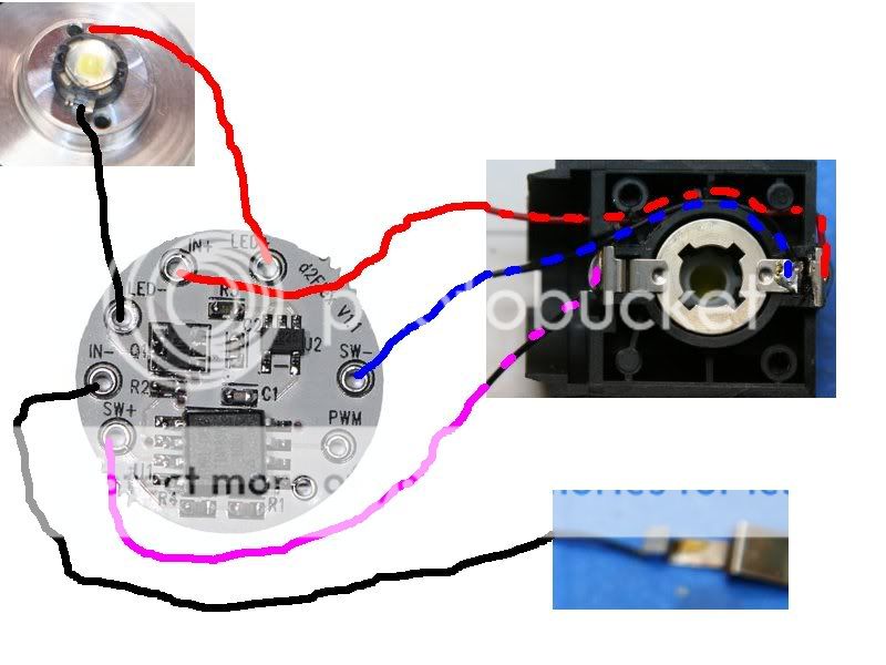
This is Will's picture. I cut like this & have the tip by mistake as well, I couldn't tell exactly where to cut.
IMG_4100.JPG


https://www.candlepowerforums.com/threads/189336


Question:

Is the reason for cutting the plastic piece to stop rotating the top
metal circle piece & defeat the mag self cleaning function?

Should I cut the side instead of the tip then?

Need Urgent help!


Last edited:

ma_sha1

Flashlight Enthusiast
Joined
Jan 10, 2009
Messages
3,042
Location
CT, USA
Re: help, Mag momentary Switch Mod messed up!

Here is a link to a post that I thought would be the right way to
cut it:
https://www.candlepowerforums.com/threads/225757

In this cut, The switch will function normally but won't rotate the circular metal piece on top,
This cut defeats the self cleaning function, which was messing C-switch up when using multi mode drivers.

This cut was for multi-mode drivers, the post didn't mention d2flex.

Is this also the right way to cut for D2Flx???


modifiedmagcswitchhw1.jpg
 
Last edited:

DonShock

Flashlight Enthusiast
Joined
Dec 28, 2005
Messages
1,641
Location
Belton Texas
Re: help, Mag momentary Switch Mod messed up!

The photo above is of a mod I did. It will not provide momentary function.
It will just help prevent false "multiple clicks" that can cause unexpected changing of modes in multimode drivers.

I took a look at Will's thread and it looks like you did the mod for the momentary switch correctly. Did you also do the part of the mod for supplying the constant power supply required by the driver? There are two different kinds of muti-mode drivers. One kind changes mode based on turning the power on and off in certain sequences. These are the ones that require "multiple clicks" and my mod works for these. But all it does is stop the rotating self cleaning feature to stop false clicks. The power still flows through the switch normally and the switch sill still start/stop power flow to the driver. These types of drivers will normally only have a set of +/- connections for power input and a set of +/- connections for output to the LED. Control of the driver happens when you turn the power on/off at the power input connections.

Wills thread details the modifications needed for the other type of driver. These drivers, such as the D2Flex, have three sets of seperate connections instead of two. One set is for power input, one set is for output to the LED, and the last set is for the switch for control of the driver. Usually, these drivers also require that the switch be a momentary type. There are two parts to Wills mods, one to convert the switch to momentary and the second to provide the additional constant power connections for the driver. If you have done the momentary part of the mod but not the power part, the driver will not work. The driver needs to have constant power to run and then needs the momentary switch input to change modes.
 
Last edited:

wquiles

Flashaholic
Joined
Jan 10, 2005
Messages
8,459
Location
Texas, USA, Earth
+ 1 to Don's reply. Spot on perfect.

The OEM switch is a latch type. It stays either ON or OFF. It is NOT a momentary switch. However, if using a driver from TaskLED, the switch has to be modified so that it no longer latches to the ON position - it has to be modified to become a momentary only switch. This way, when you press the switch, the electrical contact closes, but when you release the switch, the electrical contact opens - this is exactly what the drivers from George need ;)

Will
 

ma_sha1

Flashlight Enthusiast
Joined
Jan 10, 2009
Messages
3,042
Location
CT, USA
Thanks for both Don & Will,

I am still waiting for some Tef. wires to come, so I have not connected to the d2flex yet.

I have one more question.

From Will's thread, the Stock switch was connecting positive to the bulb
when on, but for the Momentory mod, the positive was cut & the other side where it used to go to the bulb is now going to the the d2flex.

So, when one hit momentory on, I assume the round circle piece is pushed up to make a connection?

But I don't understand the two parties of the connection thou,

There are three wires coming out,

A. is battery posi. going to the d2 flex direct & by passed the switch all together.

B. Is connected to one of the old switch contact point
C. is connected to the negative via. the switch point touching the tube?

Is momentary suppose to make a connection between B & C?

thanks a bunch
 

ma_sha1

Flashlight Enthusiast
Joined
Jan 10, 2009
Messages
3,042
Location
CT, USA
I think I got it, Looks like will hard wired the other side of the switch to the
negative, so that the momentary will make a connection between B&C.

Thanks Guys,

This is really tricky, I hope this is my 1st & last momentary C switch DIY :eek:
 

DonShock

Flashlight Enthusiast
Joined
Dec 28, 2005
Messages
1,641
Location
Belton Texas
I cut and pasted some photos from Will's thread and the TaskLED website to create a little mockup photo in MSPaint. This should make it clearer how to wire the modified switch from Will's thread to the D2Flex driver.

Mockupforma_sha1.jpg
 

darkzero

Flashaholic* ,
Joined
Oct 7, 2003
Messages
4,459
Location
SoCal
I cut and pasted some photos from Will's thread and the TaskLED website to create a little mockup photo in MSPaint. This should make it clearer how to wire the modified switch from Will's thread to the D2Flex driver.

Mockupforma_sha1.jpg


That should be very helpful for anyone who is not familiar with wiring these. To make it easier, no need to connect the "blue line" to SW-. Just connect the "blue line" directly to the ground tab coming off the switch, it's the same connection as IN-. One less wire you will need to run to the driver.
 

wquiles

Flashaholic
Joined
Jan 10, 2005
Messages
8,459
Location
Texas, USA, Earth
That should be very helpful for anyone who is not familiar with wiring these. To make it easier, no need to connect the "blue line" to SW-. Just connect the "blue line" directly to the ground tab coming off the switch, it's the same connection as IN-. One less wire you will need to run to the driver.

+1 - That is exactly how I do mine ;)

Will
 

Justin Case

Flashlight Enthusiast
Joined
Mar 19, 2008
Messages
3,797
That should be very helpful for anyone who is not familiar with wiring these. To make it easier, no need to connect the "blue line" to SW-. Just connect the "blue line" directly to the ground tab coming off the switch, it's the same connection as IN-. One less wire you will need to run to the driver.

Does the wiring in the drawing actually work? In the D2FLex documentation, the momentary switch has to make or break a connection between SW+ and IN-. I don't see how that can occur the way the wires are connected in DonShock's drawing. The "blue line" isn't grounded to anything. Now, if you connect the "blue line" to the ground tab, as darkzero recommends, then I can see how the momentary switch can make or break electrical contact between SW+ and IN-.

What am I missing?
 

darkzero

Flashaholic* ,
Joined
Oct 7, 2003
Messages
4,459
Location
SoCal
Does the wiring in the drawing actually work? In the D2FLex documentation, the momentary switch has to make or break a connection between SW+ and IN-. I don't see how that can occur the way the wires are connected in DonShock's drawing. The "blue line" isn't grounded to anything. Now, if you connect the "blue line" to the ground tab, as darkzero recommends, then I can see how the momentary switch can make or break electrical contact between SW+ and IN-.

What am I missing?

It does in fact work. The momentary switch makes contact from SW+ to IN-. SW- & IN- are the same electrical path & that is where the blue line would ground out. Since there is already a ground connection at IN-, that is why there is no reason to run the SW- connection from the switch to the driver. It's easier just to connect it to ground at the switch when used in a Maglite application.

I'm sure there maybe other applications where SW- would be useful but I haven't came across a build like that yet. Even in the Novatacs & HDS mods I eliminate the SW- connection.
 

wquiles

Flashaholic
Joined
Jan 10, 2005
Messages
8,459
Location
Texas, USA, Earth
It does in fact work. The momentary switch makes contact from SW+ to IN-. SW- & IN- are the same electrical path & that is where the blue line would ground out. Since there is already a ground connection at IN-, that is why there is no reason to run the SW- connection from the switch to the driver. It's easier just to connect it to ground at the switch when used in a Maglite application.

I'm sure there maybe other applications where SW- would be useful but I haven't came across a build like that yet. Even in the Novatacs & HDS mods I eliminate the SW- connection.

+1

That is also how I wire mine as well ;)

Will
 

Justin Case

Flashlight Enthusiast
Joined
Mar 19, 2008
Messages
3,797
It does in fact work. The momentary switch makes contact from SW+ to IN-. SW- & IN- are the same electrical path & that is where the blue line would ground out. Since there is already a ground connection at IN-, that is why there is no reason to run the SW- connection from the switch to the driver. It's easier just to connect it to ground at the switch when used in a Maglite application.

I'm sure there maybe other applications where SW- would be useful but I haven't came across a build like that yet. Even in the Novatacs & HDS mods I eliminate the SW- connection.

I see how your wiring configuration would work fine. The wire from the bottom contact goes to the ground strap of the switch, and then that is connected to IN-. So when you hit the Mag momentary switch, you momentarily connect SW+ and IN-. My question is with respect to the wiring configuration in DonShock's drawing. He does not have the black wire from the bottom contact going to the ground strap. Instead, that wire goes directly to SW-. But that wire isn't connected to ground as far as I can tell. When you hit the momentary Mag switch, the lower and upper contacts are connected as usual, but that doesn't make a connection between SW+ and IN-. The blue wire does not look like it is connected to the ground strap in any way. The wire from the ground strap still goes to IN-, but it bypasses the momentary switch, so I don't see how a brief press of the switch can cycle the D2Flex. I figure I must be missing something obvious.
 
Last edited:
Top