Optical comparator light modification

ddv

Newly Enlightened
Joined
Oct 15, 2010
Messages
7
Gee it's lonely in this forum but I can't deny that this is a rather special application. I hope some of the flashlight modder guys stumble in here because I think this is up their alley. :)

I have an old optical comparator (used to project a magnified image of a part for measuring and quality control) that was discontinued 26 years ago. Parts are no longer available from the manufacturer and the bulb for the surface light is no longer made. The PO apparently modified it to accept a different bulb, so even if I get a NOS light, the correct socket is missing and the bayonet socket bulb that's in there now is far too dim. Here's a picture of what I have:

existing_surface_light.jpg


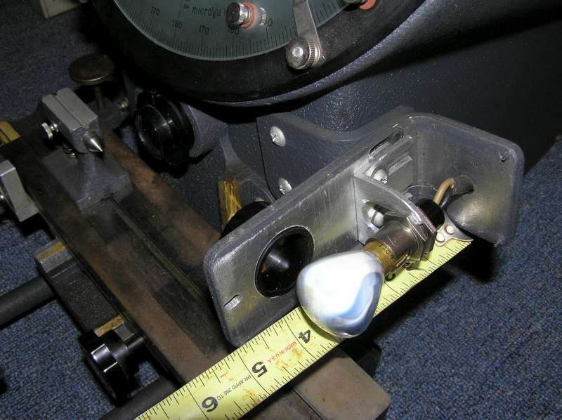
From my research, the original bulb would have been a 50 watt pre-focused halogen, probably around 900 lumens and delivering and estimated 16,000 foot-candles at 6" (the distance from the bulb to the focal point). As you can see, the fixture incorporates a lens to tighten the beam and further intensify the light at the focal point of the imaging lens (marked by the centre point on the anvil in the picture). Before the existing bulb burned out, the lens was turning it's scattered 2000 f-c into a 10,000 f-c spot at the focal point (according to my LunasixF.)

The lens barrel ID is 1.070", the case inside depth is 1-15/16" and inside length is 4-7/8". The power is supplied from a simple CT transformer rated 6.3 volts at 3.5 amps which delivers a no-load voltage of 7.3vac.

Since I have to cobble something together, I was thinking that perhaps a modern high-output LED array might be suitable. I have a lathe and mill, so I can easily fabricate suitable heat-sinks and brackets. Browsing this board led me to the dealextreme website and the "SSC P7 C-Bin LED Emitter with 21mm Heat Sink Base" seems to fill the bill for light output and the "Regulated CV/CC LED Driver Circuit Board for Cree MC-E/SSC P7 Emitters (8.4V Max Input)" would seem to be usable given my power supply. They also offer two integrated modules, but on one the reflector is way too large and the other has a strobe function -- not desirable in this application!

There are two reflectors that seem to be small enough: the "26.5mm Aluminum Reflector Drop-in Module Set (without Emitter)" and the "18.5mm Smooth Aluminum Reflector". Can anyone tell me if either would be suitable for use with the P7 emitter?

The beam gets focused down to a spot, but the end result is magnified 20x. I am assuming that a smooth reflector will be less likely to introduce variations in light intensity. Have I got that right, or would a textured reflector be better to average out any variations from the emitter itself? In that vein, should I look at putting a diffuser lens between the emitter/reflector and the focusing lens?

With regards to the power available: the driver module voltage looks right, but doesn't specify DC or AC and looks like it was designed to sit on a battery terminal. Will 6.3vac damage it? Obviously the diode will only emit light half the time if powered by AC. Should I add a bridge rectifier and maybe a couple of filter caps or would that be unnecessary overkill?

Am I missing anything?

Thanks for your time.
 
Last edited by a moderator:

ddv

Newly Enlightened
Joined
Oct 15, 2010
Messages
7
Hmmm. It would appear that I am not allowed to post links to the items I'm looking at. Ok, someone who knows the answers to my questions probably knows what a P7 and driver looks like anyway. But let me rephrase the reflector question:

What reflector would you recommend that will fit the P7 emitter's light pattern and direct the maximum amount towards the 1" lens as evenly as possible?
 

DM51

Flashaholic
Joined
Oct 31, 2006
Messages
13,338
Location
Borg cube #51
Welcome to CPF, ddv :)

You've posted in an obscure part of the forum - I hope you aren't disheartened by the lack of response to your very specialised question.

I'll move it to H&M - let's see if someone there has an idea for you.
 

ddv

Newly Enlightened
Joined
Oct 15, 2010
Messages
7
I'll move it to H&M - let's see if someone there has an idea for you.

Thankyou.

(I did wonder if that would happen but it seemed like the most appropriate forum at the time.)
 

Mick

Newly Enlightened
Joined
Mar 1, 2005
Messages
117
Location
TN, USA
I think a Luminus Devices SST/R 50 or 90 would work better in you application as the SSC P7 is composed of 4 separate dies and there is a gap between them. This would mean you would need a diffuser to eliminate the dead cross created by the 4 die gap and diffusers are very inefficient, like 10% transmission. Look for someone that makes a SST50 pill with a driver. You should not need a reflector as the original setup just focused on the filament of the bulb. You are throwing a lot of light away but this is better than a bulb which radiated over 360 degrees.
 

ddv

Newly Enlightened
Joined
Oct 15, 2010
Messages
7
I think a Luminus Devices SST/R 50 or 90 would work better in you application as the SSC P7 is composed of 4 separate dies and there is a gap between them. This would mean you would need a diffuser to eliminate the dead cross created by the 4 die gap and diffusers are very inefficient, like 10% transmission. Look for someone that makes a SST50 pill with a driver. You should not need a reflector as the original setup just focused on the filament of the bulb. You are throwing a lot of light away but this is better than a bulb which radiated over 360 degrees.

Ok, I've spent the last couple of hours chasing down and reading datasheets. It has been educational! For example, now I better understand what is meant here when I see references to "bin such-and-such".

I tracked down exactly one drop-in assembly for the SST-50. My first thought was that the driver maximum voltage input is lower than what my transformer is delivering, but then I realized that the transformer is centre-tapped and slapped myself upside the head :duh2:. A full-wave bridge and a couple of filter caps and I should be good to go, right?.

So, it looks good on paper, price is pretty good at $37 including shipping, but reading a couple of reviews it sounds like the included driver is a bit short of the mark. The SST-50 datasheet rates it at 1.75 amps, but the review says the driver is only delivering 1 amp. So (depending on which bin is supplied -- it's not specified) the light output could be as little as 250 lumens. I realize that the output is directional (100°), but the original bulb would have had a reflector to pre-focus it too.

That SST-90 looks just about ideal for my needs. Bin M would be 850 lumens (min) and bin N would be 1000 at 3.2 amps. Pricey little devils at $36 and $39 respectively, plus $22 shipping, but not as pricey as the driver: $42. Nice though -- input from 90vac to 220vac, so I could just by-pass the transformer and be done with it. Unfortunately, the driver is not currently available and there's an 8 week backorder. :(

How would it work to use the P7 driver I mentioned in my first post with the SST-90? Any problems mixing and matching like that? From what I think I know: that driver is regulated at 2.8 amps, instead of 3.2, so the light output would be down a bit. The graph looks pretty linear, which makes me think that the bin N would deliver around 850-875 lumens at that current which would be pretty close to the original bulb's spec. Am I missing anything?
 

Mick

Newly Enlightened
Joined
Mar 1, 2005
Messages
117
Location
TN, USA
I think your heading in the right direction. A SST90 would give you a nice flat field source. You had trouble with posting links because you need a minimum number of posts. This discourages spam. I would be willing to help you with this but would prefer to do so via email. I will PM you with an email address.
 

Dr.Jones

Newly Enlightened
Joined
Jun 22, 2010
Messages
115
Location
Germany
How big is the area you want to illuminate with those 170kcd (~16000 f-c)?

The luminous power of that LED doesn't need to be 900lm to illuminate that spot with the same illuminance, because a LED doesn't emit into all directions but more forward. To catch the same amount of light with that lens, a bit more than one quarter of those 900 lm will suffice, say 250lm.

The other difference between that frosted incandescent bulb and a LED is the emitter size: The LED is much smaller and thus allows to concentrate it's light MUCH better.

Since I don't know the exact distances (emitter-lens, lens-target), i do some guessing here, so it's only a rough estimation.

Suppose you use a 250lm LED, 1mm² die size. The lens will catch about 15% of that, so 40lm. These get focused on a spot of, say, 3mm*3mm =~10mm². That results in an illuminance of 4 lm/mm² or 4 Mlx (megalux) or 400000 foot-candles. (But there will be some losses, too. - With the LED dome, the spot will be even bigger, with XR-E more that with XP-E, without giving less illuminance.)

Feel the power of high-luminance light sources :)
 

ddv

Newly Enlightened
Joined
Oct 15, 2010
Messages
7
Dr. Jones,-

Sorry, I guess I should have put those details in the original post. My Bad. The area to be illuminated is about a 3/8" circle (about 80 mm²) at a distance of 4.5" (115mm) from the lens and the bulb filament is about 1.5" behind the face of the lens.

The problem is that the area under illumination is being magnified 20 times and then projected on a frosted glass screen to be viewed in ambient room lighting. The original bulb was pre-focussed, so had characteristics similar to an LED. The one that's in there is not the original -- it has no reflector, it's the wrong base and power, and what appears to be frosting is the smoke that escaped the filament when the bulb burned out. It's only use was to get some measurements for comparisons. Based on the 5:1 intensification of that "test" beam, I assume the proper bulb would deliver 16,000 x 5 = 80,000 foot-candles at the focal point. (re-reading the original post, I don't think I was very clear on this either. I only quoted the estimated output of the correct bulb alone, not what I calculated the intensification to be after the lens. Sorry.)

Think in terms of a film or slide projector. They need a very bright, focused beam of light and still are only clear in a dark room. Of course, the bulbs used in those get hot enough to burn down the house and have life spans measured in 10's of hours. So LEDs still have a huge advantage.

So if we correct your assumption of the area to 80mm², the intensity of the 250 lm LED at the focal point would then be 50,000 foot-candles, or about 62.5% of the original bulb, correct? From there, can we calculate that a 400 lm LED would be pretty close? Maybe round that up to 500 lm to account for the losses you mention?

Thanks for the advice.
 

MikeAusC

Enlightened
Joined
Jul 8, 2010
Messages
995
Location
Sydney, Australia
A bare SST-90 illuminates an area about 3/8 dia, 5mm in front of the LED - no optics to add, no losses.

So that's about 2000 lumens where you want it.
 

John_Galt

Flashlight Enthusiast
Joined
Feb 20, 2009
Messages
1,835
Location
SW, PA
If this is for distinguishing differences in surfaces, you're gonna want a high CRI light source. Regular cold/neutral white LED's usually have a CRI of under 80 (on a scale of 100, 100 being best, or sunlight), compared to an incandescent s 95+ CRI.

I would go with a Seoul Semi Conductor P4 High CRI LED. Or one of the Nichia High CRI offerings. These will be closer to incandescent in appearance, and allow better distinction between materials.

Follow it up with a TIR optic (Total Internal Reflection), and/or an Aspheric lens (not as efficient as any optic), and you should be set.

You'll notice that most High CRI LED's have noticeably lower output than their low-CRI brethren, but because they are easier to distinguish things with, you'll appreciate them quickly.
 

MikeAusC

Enlightened
Joined
Jul 8, 2010
Messages
995
Location
Sydney, Australia
If this is for distinguishing differences in surfaces, you're gonna want a high CRI light source. Regular cold/neutral white LED's usually have a CRI of under 80 (on a scale of 100, 100 being best, or sunlight), compared to an incandescent s 95+ CRI.

Here's a quote - though from someone trying to sell LED lighting - http://www.cofan-pcb.com/index.php?option=com_content&view=article&id=103&Itemid=129

"Manufactures utilize machines to inspect their products for quality and consistency. LEDs offer smaller size, better control of the light spectrum, and longer life operation compared to all other traditional light sources. Traditional light sources have a wide variance of light spectrum, resulting in less accurate measurement of products attributes. LEDs improve accuracy while fitting into smaller spaces and requiring far less maintenance and repair, more than 20 times less"
 

ddv

Newly Enlightened
Joined
Oct 15, 2010
Messages
7
Thanks for the tips guys. However, in this case, the images will be primarily monochromatic and the lighting high-incident -- the application is inspecting/measuring things like fine threads and gear teeth. I suspect the CRI would be of more importance in other applications. A slide or film projector, for instance, where colours must be distinguishable.
 
Top