AlanB's Drop In Dream Come True - Regulated Driver!!

LuxLuthor

Flashaholic
Joined
Nov 5, 2005
Messages
10,772
Location
MS
Note: Second high power Modamag 250W bulb testing review here.

Many of us have been waiting for a quality regulated incan bulb holder, since the AWR Hotdriver debacle. AlanB, WQuiles, and JimmyM have been working steadily over the last year to bring a custom programmable driver (various projects and threads are linked here) so you can set an optimal voltage to drive a particular incan bulb, without flashing it, or running it direct drive off the batteries. This pursuit goes back to Willie Hunt, Newbie, and more recently JS, AWR, and AW which have made other versions that are not on the same scale of prowess and flexibility coming from a volunteer colaboration from many.

I was extremely privileged to be sent the first, programmed Mag D drop-in model completed by AlanB to stress test and find any problems or improvements which I have started working on. I am primarily using this to test bulbs in the 7.3V range, powered by 2 x IMR 26700 safe Lithium Manganese (Emoli brand) cells, as well as 6 x NiMH cells.

First bulb is the Philips 5761 which many have worked on trying to get close to the optimal 7.2 to 7.4V without flashing it. I will be posting functional testing results in this thread as programmed by Alan with parameters listed here.

I used partially charged cells testing all the button functions already, and they work as listed, and quite satisfactorily. Low battery shutoff for these two cells shutoff at 6 V, and it came too soon!!! While I get my cells all nice and charged up, I thought I would post these images I took to give you a pretty good idea of how this looks, compares, and works. Consider this more as eye candy, with functional results coming soon.

These photos are intentionally larger sizes (500-900KB) so you can see more details. So be patient.

Size Comparison Section


Fit Section


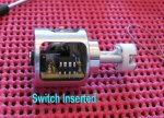
Inserting button and programming stick
 
Last edited:
.... this is giving me more reason to start poking at incan,too!

I'm even more intrigued now.. seems incans have suddenly become regulated!

argh! high school student wallet null and VOID.
 
Glad to see it arrived safely. Nice to see that it fits in the various bodies. You have quite a collection! Great Photos, too!

SAE vs Metric Threads


The socket mounting is presently 4-40 threads. We can change that to metric if folks would prefer. What size metric? I chose the 4-40 since the tooling was available at the hardware store and I wasn't sure I could tap the prototype with metric without breaking the tap with that finer metric thread. I'll have to discuss it with the machinist, but I doubt if he cares much one way or the other.
 
Last edited:
LuxLuthor, great review/first impressions ;)

Alan, congrats again on this awesome milestone - you the man :twothumbs

Will
 
Not sure why but I was thinking this is the MDPHD (M@g Dropin Programmable Hotwire Driver). Has sort of a ring to it...

How do folks feel about SAE vs Metric on the bulb mount threads? Should we discuss that in the other thread or here?? This is Lux's review thread.
 
LuxLuthor, in your history of regulated incan it would appear you have neglected Winnie's excellent (but sadly low quantity run) of programmable regulators, which was designed to mate perfectly with the Kiu socket. That's not to take anything away from Alan B, et. al., whose creation is most welcome! Just that given your mention of others in historical context it seemed strange to omit that one.
 
Alan, the only aspect of the screw thread that is important is being able to make it shorter than this size to fit various reflector/head sizes, so an alternative would be to send with extra supplies of 2 shorter screws and tubes. Probably better way to go, since not everyone has KIU kits that supplied those brass legs.

Edit: Testing the various combinations of button clicks and stored memory settings which I now realize only get stored in memory when using the ramp up/down feature which I like. Takes about 6 seconds to ramp from one end to other. I like this short 200ms soft starter when turning on. I like the feel of this clicker under the rubber boot, and being closer to the boot than AW's multi-level which requires a deeper pressing.


Despite the seemingly better looking quality of the Osram bulb holder, as I mentioned to you, its wire looks more like 20AWG than the KIU 18AWG, which would help explain the 41mΩ vs. 31mΩ, respectively when tested with jumper in bipin holes (using 5" lengths for both as KIU ships with)

Also, while it holds onto larger G6,35 (i.e. Osram 64623 100W) bipins, nicely...it is too loose for holding G4 bulbs. I have to put a minor bend in G4 legs to have them be securely held...which isn't hard to do.

LuxLuthor, in your history of regulated incan it would appear you have neglected Winnie's excellent (but sadly low quantity run) of programmable regulators, which was designed to mate perfectly with the Kiu socket. That's not to take anything away from Alan B, et. al., whose creation is most welcome! Just that given your mention of others in historical context it seemed strange to omit that one.

Milky, it was just a bit before I arrived on the scene and knew the difference between an amp and a hole in the ground! My subsequent reading about it in this thread indicated a significant problem in the software that was not fixed....so while Winny did some great work, it did not sound like it was a "finished & working product" the way Willie Hunt did for the JS M6R, AWR did for Hotrater, or AW did with soft starter multi-level switch. I even bought one of these from JimmyM, and did not find it to be workable with that bug.

I was in fact, the one who sent a PM to Winny to tell him about this collaborative AlanB/Jimmy/WQuiles project, and prompting his last post on this forum.

For reference, the PIR is linked in the main project thread here.
 
Last edited:
Test Setup

Flashlight Host


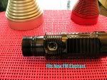
I used this 2 1/4 Mag D from FM which was a perfect length for 2 x Emoli cells. Here you see with rulers that battery tube length is the same as with an AWR Hotrater used on left.


I measured the distance from back of switch to lip edge of Mag (including back threads, but no tailcap) in mm, to give a good idea of how much battery room you have and how it compares with other switches we have been using:

  • AWR Hotrater - 159mm (typical of KIU type setup, retaining spring clip removed)
---- All others below have retaining spring clip inserted in Mag and switch pushed up against it from bottom ----

  • AlanB - 160mm (From center contact screw 156mm)

  • Stock Mag Switch - 160mm

  • AW - Multi-level Switch - 164mm (From center contact post 162mm)

Battery Source
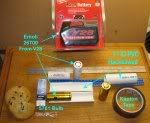
I used the Emoli 26700 cells from the Milwaukee V28 Tool pack as shown below. Two of them fit perfectly in the FM light by using a simple 1" (Internal Diameter) PVC pipe that was "clamshelled" with a hacksaw (otherwise batteries are extremely tight and have no heat expansion/dissapation capability). Cardboard around battery must be removed, and PVC halves can be taped or not.


The setup Alan provided was for a 2S cell number, and these batteries have normal Lithium 3.7V rating, charged up to 4.2V. They generally store about 2600-2700mAh of output capacity. They perform well at high current demands which I needed for the bulbs I tested. AW has his own version of these cells that are 20mm shorter which can also be used with similar characteristics.

It is important to avoid over-discharging these "safe Lithium Manganese" chemistry cells below 2.8V per cell, so Alan set the driver to shut off when the total voltage of the two cells drained to 6.0V

Bulbs Used
Philips 5761 was primarily used. We did not want to start out with the higher watt/amp bulbs in testing this prototype. However, the 5761 was chosen because as the link shows, this bulb has a great lumen output, but a very narrow range & a requirement for a more robust current output than most Welch Allyn bulbs. It uses approximately 5.5 Amps at 7.3V

In the past, many attempts to maximize this bulb without flashing it failed without using the AWR regulation, or various Rube Goldberg configurations with NTC's, resistors, diodes, etc.

Despite the higher quality appearance of the Osram bulb holder, it was not as effective at holding the G-4 size bulbs such as the 5761, so a slight "kink" was made by placing bipin pins on a wood 2x4 (glass off the edge), and lightly tapping down on a screwdriver blade poised over pins. This avoids damage to the glass envelope.

Other bulbs that could tolerate a peak 7.3V range were also tested, and all worked as expected. These can be reviewed in this destructive test thread if desired:
Osram 64250, 64275, 64430 (& Tungsram 56580 version)

Welch Allyn 1111, 1160
Function & Performance
General Observations
I used the settings Alan described in this post. He programmed this prototype before sending. I did not do any programming changes, and Alan is still tweaking and adjusting the current version of the software.

Most of my testing used the Philips 5761 bulb, consisting of 3 complete charge cycles of the Emoli cells, and numerous variations of buttons to test all programming. Run times with various output power settings were well over 30 minutes which correlates with a 5.5A draw on 2.6Ah battery source, considering my variable settings.

I took a 45 min dogwalk outside in a light mist/rain which exposed the light to humidity, but it did not get dripping wet. No problems were noted, except two alarmed skunks digging for grubs who did not appear to enjoy the lumens. :devil:

Two more complete cycles were done to test long run times on max (7.3V) with the Osram 64430 bulb which draws an even higher 6.5 Amps. Head was removed, and light used in "candlestick" mode. It got hot on upper outside, apparently mostly from bulb radiation, approximately 110-115°F (by Fluke 179 & Sentry ST-650 Laser Thermometer), but not too hot to hold. Each charge with this bulb lasted approximately 21-22 minutes on full power, and also correlated with battery capacity.

Neither of of these last two runs shutoff at 10 mins as Alan indicates he programmed. There was no noticeable drop off in intensity, but I did not keep a light meter to verify. I did use a faint object shadow that I could only see on Max, and it was always visible on these long Max runs.

First round, I manually turned it off after about 14 minutes as it got quite warm/hot in upper switch area on outside body. I let it cool about 5 mins, and again ran it on Max for another 6 minutes before it auto reduced to Med, then shut off after about a minute.

Exhausted battery voltage was always lower in the front battery in all instances. This next to last run had 3.01V & 3.41V in Front/Rear cells respectively. After 5 mins they recovered to 3.36V & 3.72V

The last of these cycles with 64430 started with 8.26Vbat (cells closely matched), and ran non-stop unattended on maximum for exactly 19::55 before switching to medium output. It then shut itself off at 20::48 sec. xxx minutes. Immediate removal of this different set of cells showed 3.08V & 3.32V recovering to 3.38V & 3.68V after 6 mins.

Button Functioning
I verified that the feel and reliable "clickability" under the rubber boot worked better than I expected. There was no problem doing double, triple, or 5x clicks to activate functions, and without false clicks. The button has a very nice and responsive feel to it. I pressed lightly, and firmly to test for possible button damage, and have subjected it to at least 1,500 clicks!! it appears to be working just as well as upon arrival. I like the idea however, that the button assembly could be replaced in case it is eventually damaged.

1) Memory stored light setting only happens when ramping up/down function is used. Once Alan told me that is the ONLY way to store a custom setting followed by off, then single click on to use stored setting, it worked 100% of the time.

2) Upon insertion of batteries, from off single click gives medium setting (Vmax + Vmin)/2. So medium voltage setting is (7.3 + 2)/2 or 4.65V

3) From off, Single click held down always gives low (2V) setting. This is a pretty sickly orange, but may be useful reading in a tent. Most incan bulbs just look pretty bad when set so low, and in this case I would likely bump it up a volt. Every bulb is different.

4) From off, once memory setting is made, single click always gives memory setting.

5) From on, single click always turns light off.

6) From on, single click held down, either starts ramp up or ramp down. Releasing yields stored memory setting for next single click on after turned off. Each Subsequent single click held down from continued on ramps in alternating up/down directions, and entire range from 2V to 7.3V takes 6 seconds.

7)(This is an edit change) With freshly charged batteries, from Off, double click always gives medium (4.65V); From On, double click always gives Max ....still troubleshooting. This is the behavior with the 6.5Amp Osram 64430 bulb. If I switch to 5761 5.5A bulb, then it gives Max from double click on or off.

Also am now noticiing with 5761, if I ramp up to Max, click off to store, the Max reading is stored unless I let it sit off, unattended for about 60-90 sec, then memory of Max fails as single click puts it to Med. However, if then followed within a few seconds by off & repeat single click, it now goes to Max, and keeps going to Max on single clicks, followed in close succession.

Now this is appearing to be an intermittent memory storage failure if left sitting off for 60-90 seconds. Repeat attempts to reproduce failure of memory to keep Max after sitting 60-90 sec as same batteries are run down do not happen...in other words after initial fresh battery install runs down, the Max memory stored reading works.

If I go back to 6.5Amp 64430 bulb with same batteries (disconnect/reconnect tailcap), now even this bulb from off goes to Max on double click, and memory stored Max stays working after 2+ mins in off.

This appears to only happen with freshly charged batteries

8) From On or Off, triple click always gives medium

9) From Off, 5x clicks gives medium flash and locks light off. Light appears to be dead.

10) Deactivate locking with another 5x sequence (again medium flash verifies change). Very handy to keep high power fire-starting torch lights disabled when sitting around 'flashlight noobs.'
Voltage/Amp measurements
I'm not sure how useful this will be, as my Fluke 179 does not do True RMS

1) Sticking probes in bipin holes gives 2.686V no matter which single/double/triple click setting.

2) With 5761 bulb in place, I carefully touched probes to sides of legs and got readings of:
Low - 1.024V
Med - 2.678V
Max - 6.921V
3) With 5761 bulb in place, I switched to Amp mode, removed tailcap, pressed Neg into bottom of battery, and Positive lead touching bare side & got readings of:
Low - 2.02A
Med - 3.08A
Max - 5.48A
Summary & Suggestions
1) Overall, this driver KICKS ***! Especially remembering that it can be programmed to do all these functions at different voltages, and much more.

2) I like the feel of this button, and the method of the memory position storage. The functions of all the clicking more than meets my needs. I suppose some may want SOS or rapid blinking since so many LED's have it, but I didn't miss it. The lockout setting is brilliant and gives an added measure of safety.

3) I could not test the 60C (140F) temp shutoff, and I could not think of a viable/safe way to hook up parallel bulbs to increase current.

4) Not sure why the 10 min unattended shutoff didn't work, but I think that is the only issue I would consider a software bug. Maybe it thinks it is in the Pacific Time Zone. :D

5) The battery shutoff protection is just wonderful to have with these cells. I'm not sure why the back cell always drained lower than front, maybe has something to do with front rounded screw giving less contact area, or electrons flowing from positive end to negative? I might even consider setting to shutoff a bit higher, or your plan to change to shutoff at half of power might have a little better buffer. In all cases, the lowest any of my cells were showing opening and testing immediately after shutoff was 2.95V

6) Rounded screw contact on bottom of switch would take less battery space and give better contact if it was flat, rather than a round head screw. This will also improve current flow by giving more contact surface.

7) Thumbs down on the Osram bipin holder if you plan to use this for G4 pin size bulbs. It would be fine for GY6,35 (typical Osram 100W bulb). I'm thinking this wire is 20AWG, not 18. If so, that is not ideal for higher watt bulbs, despite the rating stamped on bottom.

8) The aluminum sled and open design appears to work very well in terms of fitting all the lights I have. It easily fit in all my mags. Not too tight, not too loose in terms of width. Being able to keep in the retaining spring gives extra protection from batteries pushing switch assembly forward which is always a concern if KIU assembly (i.e. in AWR Hotdriver) has the setscrew loosen. I always drilled a slight hole for setscrew to give it better anchoring, but no need with spring clip useage.

9) Warning should be given to people about static electricity, and grounding themself before handling switch or programming components. I think as long as people are careful, inserting the switch/programming stick onto the pins should hold up. It is a little hard to hold onto and make sure button switch is lined up with pins once assembly is inside light and set screw tightened. People may need to use tweezers and small light, but not a big issue. Switch removal with wire loop was clever and reliable. The rubber boot fit over switch in every light I tried it in.

10) The 200ms soft starting is wonderful. Love it like this.

11) I didn't yet check the voltage drive as you described in PM under direct drive scenario, but think I covered all the other items. Let me know if that is important, and I can still try it later.

12) It seems like there should be an even "Baker's Dozen" but I can't think of anything else except that I should now get to bed. I didn't proof this for typos. Thanks again!
 
Last edited:
Wow. Lots of effort in testing. Thanks, Lux.

I have not tested the timeout shutoff recently, apparently a bug crept in there. I will look into that.

The way I tested the overtemperature was to lower the setting and reprogram, and keep doing that until it "went off". I have not done that recently. Lux cannot do that yet since he doesn't have the code.

The battery positive contact is a 6-32 screw, so we can use anything there. I used a hex screw in the first prototype (that was #4), but with the FM battery holder it made a ring on the convex tip. That battery holder does not have a flat area to contact.

I would like to find a thin-head flat top flatted hex screw, that would provide the flat contact and install with a wrench. I would prefer brass as it is half the resistance of steel. I have not found one. We could make one but that is costly.

It would be interesting to calculate the approximate RMS from the average measurements and the loaded battery voltage to see how close they are. This is not completely accurate unless the waveforms are square and the battery voltage is accurately known, but it should be close. Another way is to compare the light output with the same bulb on a power supply. This is not critical anyway.

I will work on getting the code ready for Lux to try programming that will take some time due to my schedule, and a bit of a learning curve, but it will be useful to prepare some "user programming" documentation and test run it.
 
Last edited:
Lux: A wonderfully exhaustive review as usual; thank you so much for your work in providing this useful information. :thumbsup:


donn: Me to! :huh:


Alan: I agree, a flat / thin brass hex head is a good way to go, but I was hard pressed to find it off-the-shelf during the modeling phase. As you mentioned we may be looking at a custom screw for this application. Mention it to Art when he does the sleds and see what he can do.
 
Alan, note the new finding today that I put in #7 above. I was not looking for something like this previously, and only with freshly charged cells.

I will try to reproduce this again after another set of cells are done charging.
 
Alan, note the new finding today that I put in #7 above. I was not looking for something like this previously, and only with freshly charged cells.

I will try to reproduce this again after another set of cells are done charging.

Thanks for the testing, Lux.

This phenomenon is not surprising. It is the regulator protecting the bulb when the voltage exceeds its ability to measure it correctly.

When the battery voltage exceeds the ADC fullscale range the regulator cannot measure the voltage correctly. It only knows that the voltage is high, but not how high. So it cannot correctly regulate. It must make some decision or risk overdriving the bulb.

What the software presently does in this condition is to set the bulb voltage down to "mid" if it is over "mid". (Future versions of the code were changed to use half max bulb voltage rather than mid, after Lux's was shipped). This protects the bulb unless the input voltage is a lot higher than expected.

As soon as there is a load the voltage will drop and be within range of the ADC and things will work normally. Double clicking to go to high, or single clicking to memory if it is above "mid" will result in going to "mid". It really did go to "high" but immediately switched to "mid" before the softstart could ramp up, so it appeared to go directly to "mid".

When the batteries are allowed to "rest" the voltage may again exceed the ADC fullscale and the phenomenon reappear.

There are several solutions. One is to use slightly different divider resistors and make the voltage range a bit higher. I will look into selecting new values for these (it was actually already on my list to do this). I selected the resistors to use standard values originally. With the recent redesign to surface mount I have some reasonable cost 0.5% models that come in more values so we have more choices. Another benefit of surface mount vs through-hole components.

Another solution that we can do with the existing hardware is to use the 3S range instead of the 2S range. This would allow a lot more battery voltage before the overvoltage condition is triggered. Lux can do that when I get him the software and he reprograms the chip.

The multirange setup is a compromise between the various ranges and the available voltage references in the chip. It turns out the 2S range is the closest to the edge. I apparently chose it a bit too close to the edge in this case.
 
OK, the main thing is that my observation makes sense with how you set it up, and your explanation makes sense. I won't test it anymore, but did verify it happened with newly charged cells again.

OK to use the VbulbRMS = sqrt (VbattDC * Vbulb), I just took these readings with Osram 64430 6.5A bulb.

1) Removed batteries & measured Vbat 8.02V Re-installed them

2) Took bipin measurements in sequence with :cool: on.
Low - 0.578V
Med - 2.972V to 2.981 (fluctuated)
Max - 6.95V

3) Again removed batteries & measured Vbat 7.96V
4) I'm going to assume Vbat was 8.0V and doing equation for each:


  • Low Vbulb-RMS = sqrt (8 * 0.578) = sqrt 4.624 = 2.15V

  • Med Vbulb-RMS = sqrt (8 * 2.977) = sqrt 23.816 = 4.88V

  • Max Vbulb-RMS = sqrt (8 * 6.95) = sqrt 55.6 = 7.457V
 
OK, the main thing is that my observation makes sense with how you set it up, and your explanation makes sense. I won't test it anymore, but did verify it happened with newly charged cells again.​


OK to use the VbulbRMS = sqrt (VbattDC * Vbulb), I just took these readings with Osram 64430 6.5A bulb.

1) Removed batteries & measured Vbat 8.02V Re-installed them


2) Took bipin measurements in sequence with :cool: on.

Low - 0.578V

Med - 2.972V to 2.981 (fluctuated)
Max - 6.95V

3) Again removed batteries & measured Vbat 7.96V

4) I'm going to assume Vbat was 8.0V and doing equation for each:


  • Low Vbulb-RMS = sqrt (8 * 0.578) = sqrt 4.624 = 2.15V
  • Med Vbulb-RMS = sqrt (8 * 2.977) = sqrt 23.816 = 4.88V
  • Max Vbulb-RMS = sqrt (8 * 6.95) = sqrt 55.6 = 7.457V


Thanks, Lux. I suspect under load the battery voltage drops a bit.

Would the bulb survive this voltage? Is it brighter than it is on a 7.3V power supply??

edit: I did a quick spreadsheet to see what voltage drop would do to the interpretation of the RMS. If the battery voltage and IR drop in the light (before the regulator's ADC) were half a volt:

7.5V supply (instead of 8.0):

2.1V
4.7V
7.2V

The other problem with this calculation is that it assumes a nice square wave PWM pulse. Under this heavy load it is probably not quite square - the top may have some slant - so the accuracy suffers a bit. The regulator actually tries to compensate for this by taking several measurements.

Making the measurement with a very light load generally works better for this type of averaging meter. In the light load case the battery does not sag and the square waveform has a good square shape.

To make accurate RMS measurements under load probably requires an AC+DC RMS meter or one of the scopes that can measure this. The technique is to take many voltage measurements across the pulse, square them and take the mean, and take the square root of that.
 
Last edited:
Interesting indeed. I do have a question though, suppose I don't want any complex UI. Being programmable, would it be possible for one to simply use this switch a simple off/ on (at the set 100% Vout) and not have to worry about low, medium, ramping modes etc?
I like the cell voltage cutoff and the 5 click lockout and of course regulation. :twothumbs
Lux, thank you for putting so much care into your review. I know how much of a pain it can be to get good pictures sometimes. Thanks to AlanB for his great communication on the project and to those helping him develop this product.
 
A simple UI option is in the software. I have not tested it in awhile and I'm sure it will require some programming to make it work again after all the other changes that have been added but it should not take a lot of effort. If the ramping is disabled that still would leave low, medium and high. If low is set to high then you have on/off.

The double-click to high can be disabled, as can the triple click to medium. If memory mode is disabled than single click goes to high.

Lots of options. I'll add a few more to disable press to low and ramping and then I think we'll have most of the possible arrangements.
 
Last edited:
Driving home today (for many hours) I was thinking about Lux's testing results. I have a couple of questions and thoughts to add.

1) I thought the ADC range was good to 8.5V but this was based on my power supply's meter which is not the best. The question for Lux is what is the fully charged voltage of the battery pack? Clearly the ADC range is too low for this pack, which I did not expect. We can move it higher as discussed before by changing options and/or resistors, so fixing it is not hard, I'm just trying to understand what we are seeing.

2) The measurement of the output unloaded being fixed at one value makes me wonder what the mode of the meter was. These measurements should be taken in averaging DC mode to fit these equations. If it was in RMS AC mode the values are not what is needed for these equations.
 
Top